Method and apparatus for faster determination of a cell state of a resistive memory cell using a parallel resistor

a resistive memory and parallel resistor technology, applied in the field of parallel resistors, can solve the problems of errors in retrieving stored data, difficulty in storing multiple resistance levels in pcm cells, and difficulty in reading mlc cells, etc., to achieve faster readout of voltage-based cell state metrics, inherent slowness of current biasing, and fast readout schemes

Active Publication Date: 2016-05-17
INT BUSINESS MASCH CORP
View PDF26 Cites 9 Cited by
  • Summary
  • Abstract
  • Description
  • Claims
  • Application Information

AI Technical Summary

Benefits of technology

The present device provides a faster readout scheme specifically optimized for voltage-based metrics. The use of a parallel resistor and prebiasing circuit allows for a faster readout of voltage-based cell state metrics compared to conventional schemes. The prebiasing circuit reduces the effective resistance seen by the readout circuit, resulting in a faster settling time and better separation of memory levels. The small resistance of the resistor minimizes the effective resistance seen by the prebiasing circuit. Additionally, the higher sensing current for the SET state allows for a higher sensing voltage and reduces noise.

Problems solved by technology

Storing multiple resistance levels in a PCM cell is a challenging task.
Reading of MLC cells is particularly challenging as the read operation involves distinguishing fine differences in cell resistance via the current / voltage measurements.
Compared to SLC operation, these fine differences are more readily affected by random noise fluctuations and drift over time, resulting in errors when retrieving stored data.
However, the conventional technique for obtaining voltage-based metrics, using current biasing and voltage sensing, is undesirably slow as explained above.
This speed penalty associated with the conventional voltage measurement technique means that there is a fundamental conflict between the requirement for a fast random access of the memory and the need for voltage-based metrics supporting high density MLC memory.
The inherent slowness of current biasing originates in a large charging time constant due to the high parasitic bitline capacitance and the high resistance of the memory cell, in particular in a cell state having a higher or highest resistance value.

Method used


Image

  • Method and apparatus for faster determination of a cell state of a resistive memory cell using a parallel resistor
  • Method and apparatus for faster determination of a cell state of a resistive memory cell using a parallel resistor
  • Method and apparatus for faster determination of a cell state of a resistive memory cell using a parallel resistor

Examples


first embodiment

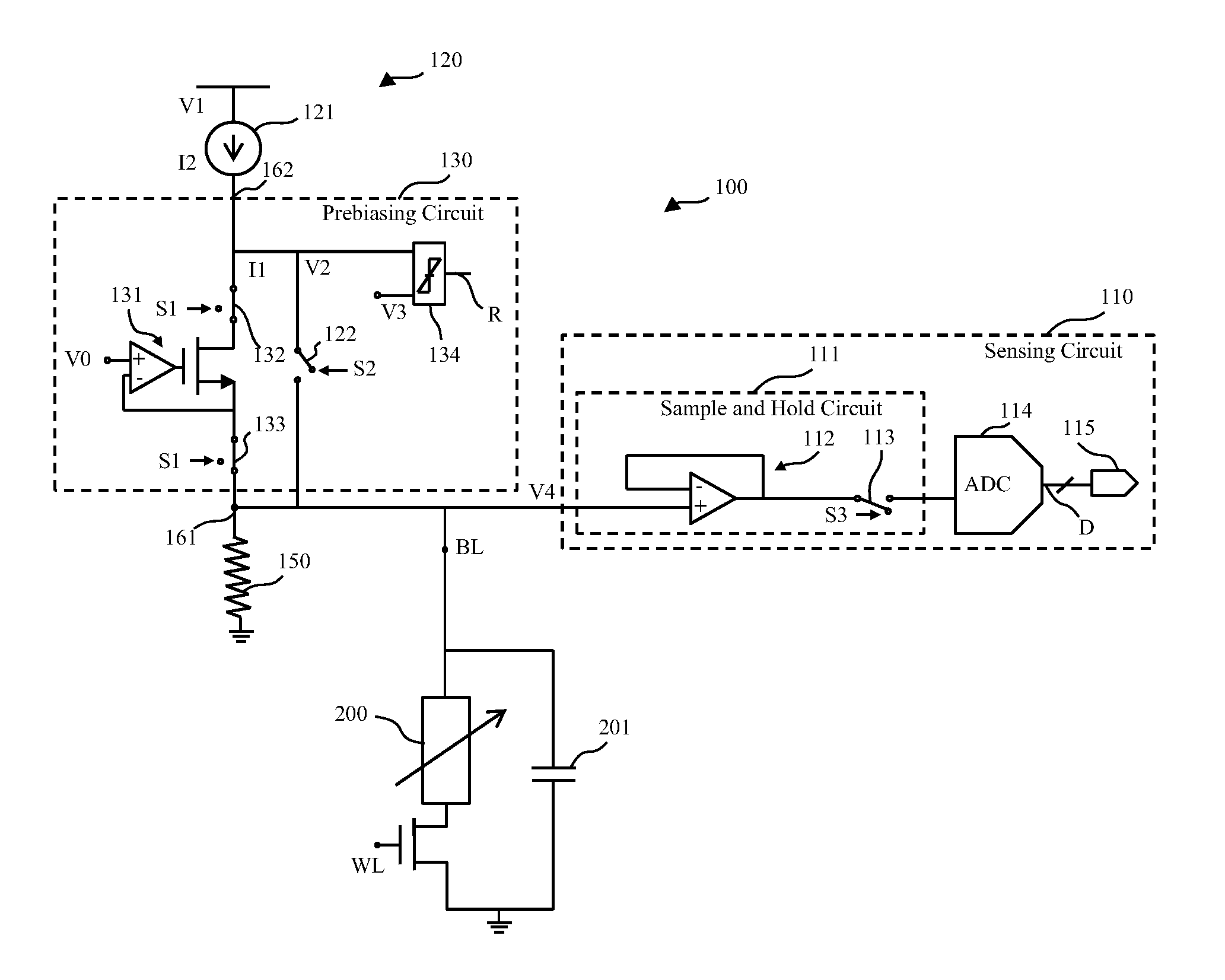
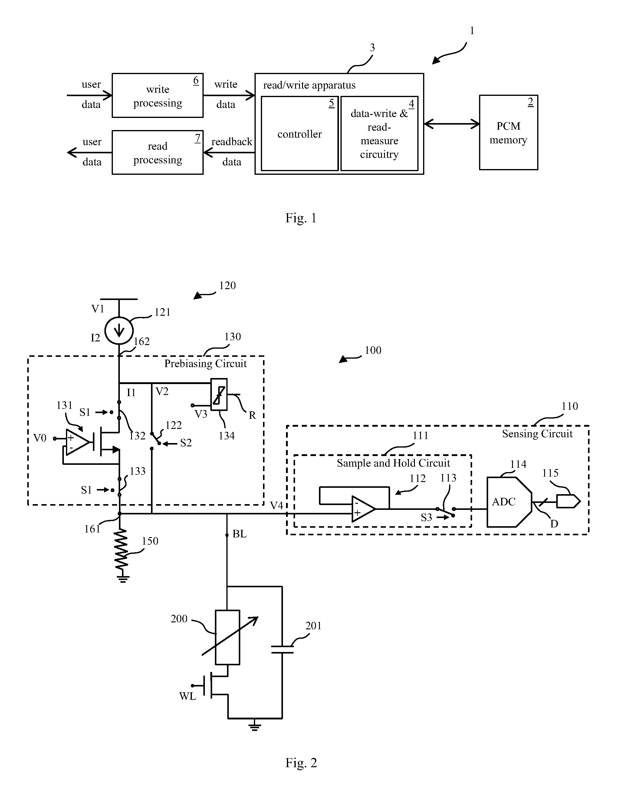
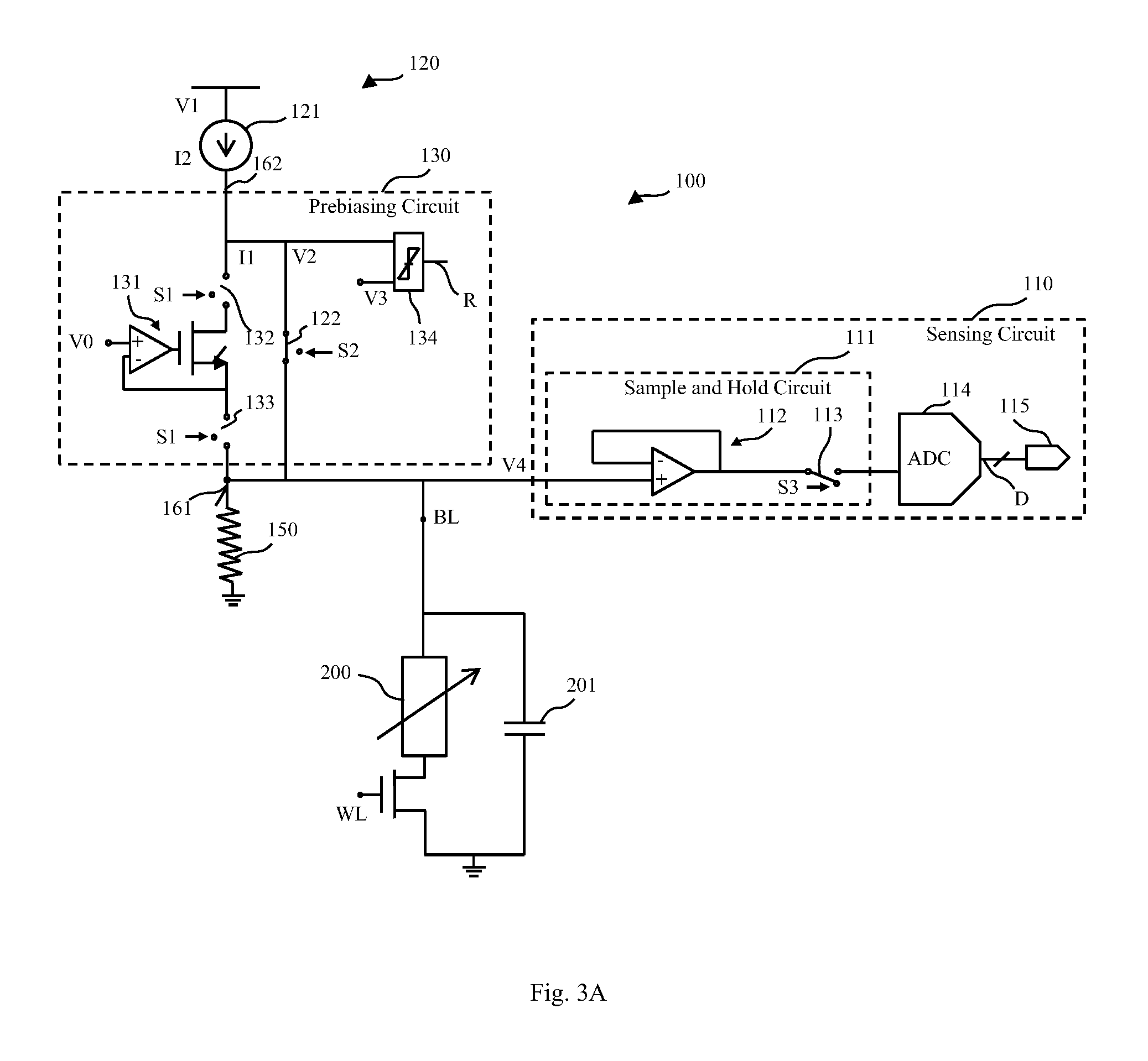
[0065]In FIG. 2, a device 100 for determining an actual cell state of a resistive memory cell 200 in a prebiasing mode is depicted.

[0066]The device 100 of FIG. 2 has a sensing circuit 110, a settling circuit 120, a prebiasing circuit 130 and a resistor 150. The resistor 150 is coupled in parallel to the resistive memory cell 200. For example, the resistive memory cell 200 is a PCM cell having a plurality M of programmable cell states.

[0067]The sensing circuit 110 is configured to sense a sensing voltage V4 of the resistive memory cell 200 and to output a resultant value D (e.g., a digital value D) in response to the sensing voltage V4. The sensing voltage V4, and therefore also the resultant value D, are indicative for the actual cell state.

[0068]The sensing circuit 110 includes a sample and hold circuit 111, an analog-to-digital converter (“ADC”) 114 and an output 115. The sample and hold circuit 111 includes a buffer 112 and a switch 113 controlled by control signal S3.

[0069]The s...

second embodiment

[0083]Further, FIGS. 5-7 show the device 100 in different operating modes.

[0084]FIG. 5 shows the device 100 in the prebiasing mode. In the prebiasing mode, the switch 122 is opened, the switch 143 is closed and the switch 113 is opened. In FIG. 5, the current flows from the voltage source 141 over the first node 161 to the bitline BL and therefore to the resistive memory cell 200. The current flow in FIG. 5 is shown by arrow A1.

[0085]Further, in the settling mode according to FIG. 6, the switch 143 is opened, the switch 122 is closed and the switch 113 is open. As a result, the current flows from the current mirror 121 to the resistive memory cell 200 over the first node 161 and the bitline BL. The current flow in FIG. 6 is shown by arrow A2.

[0086]In FIG. 7, the device 100 is in a sampling mode. In the sampling mode, the switch 143 is opened, the switch 122 is closed and the switch 113 is closed. The controller controls the sampling by the third control signal S3 applied to switch 1...


PUM


Abstract

A device for determining an actual cell state of a resistive memory cell having a plurality M of programmable cell states comprising a sensing circuit, a settling circuit, a prebiasing circuit, and a resistor coupled in parallel to the resistive memory cell, wherein the resistor is configured to reduce an effective resistance seen by the prebiasing circuit. The sensing circuit is configured to sense a sensing voltage of the resistive memory cell and output a resultant value in response to the sensing voltage which is indicative for the actual cell state. The settling circuit is configured to settle the sensing voltage to a certain target voltage representing one of the M programmable cell states. The prebiasing circuit is configured to prebiase a bitline capacitance of the resistive memory cell such the sensing voltage is close to the certain target voltage.

Description

BACKGROUND[0001]1. Technical Field[0002]The invention generally relates to a device and method for determining an actual cell state of a resistive memory cell having a plurality of programmable cell states.[0003]2. Description of the Related Art[0004]A prominent example for resistive memory cells having a plurality of programmable levels or states is Resistive Random Access Memory (“RRAM”), in particular Phase Change Memory (“PCM”). PCM is a non-volatile solid-state memory technology that exploits the reversible, thermally-assisted switching of specific chalcogenides between certain states of different electrical conductivity.[0005]PCM is a promising and advanced emerging non-volatile memory technology mainly due to its excellent features including low latency, high endurance, long retention and high scalability. PCM may be considered a prime candidate for Flash replacement, embedded / hybrid memory and storage-class memory. Key requirements for competitiveness of PCM technology may b...

Claims


Application Information

Patent Timeline
Patent Type & Authority Patents(United States)
IPC IPC(8): G11C13/00G11C11/56
CPCG11C13/004G11C11/5678G11C13/0004G11C2013/0057G11C2213/79G11C13/0069
Inventor PAPANDREOU, NIKOLAOSPOZIDIS, CHARALAMPOSSEBASTIAN, ABUSTANISAVLJEVIC, MILOS
Owner INT BUSINESS MASCH CORP
Why Eureka
Try Eureka