Integrated nanobeam cavity array spectrometer

a cavity array and nanobeam technology, applied in the field of spectrometers, can solve the problem that super-prism based spectrometers cannot provide complete separation of adjacent wavelength channels, and achieve the effect of small siz

Inactive Publication Date: 2016-05-24
PRESIDENT & FELLOWS OF HARVARD COLLEGE
View PDF16 Cites 8 Cited by
  • Summary
  • Abstract
  • Description
  • Claims
  • Application Information

AI Technical Summary

Benefits of technology

[0009]In a preferred embodiment, the present invention is a novel type of on-chip spectrometer that combines features of Fabry-Perot (FP) spectrometer with grating spectrometer. Advantages of the present invention include, but are not limited to, its small size and potential for integration of photonic and electronic functionalities side-by-side on a single substrate. In this way, the entire spectrometer module can be implemented on a very small microchip.
[0011](1) High spectral resolution to allow for accurate reconstruction of the spectrum of an unknown input optical signal.
[0012](2) Good signal-to-noise ratio which relies on an efficient collection of the input optical signal as well as effective isolation of the signal from stray light. This will allow that the spectra can be taken even with low-level input signals.
[0014]To realize this novel on-chip spectrometer and to fulfill the requirement of an efficient spectrometer, the present invention takes advantage of a high-quality factor (and high-finesse) optical resonator (similarly to FP spectrometer), but instead of sweeping the cavity resonance, it realizes a large number of optical cavities, each tuned to a slightly different wavelength. In this way, the present invention, referred to as an Integrated Nanobeam Array Spectrometer (INAS), can map the spectral content of the optical signal into spatial domain, similar to grating spectrometer.
[0022](2) Nanobeam resonators are wavelength-scale resonators and therefore they can support only one mode in the operating wavelength of interest. That is they have free-spectral range that can be much larger than that of ring-resonators that are by-design multimode. Therefore, nanobeam resonators minimize cross-talk between different spectrometer channels.
[0023](3) Nanobeam resonators can be designed to emit light vertically towards the detector array positioned above. These detectors can be integrated on the same chip which further reduces the size and simplifies the design since no additional grating couplers are needed. This takes advantage of integration of photonic and electronic functionalities on the same chip.

Problems solved by technology

Nevertheless, super-prism based spectrometers are not able to provide complete separation of the adjacent wavelength channels.

Method used


Image

  • Integrated nanobeam cavity array spectrometer
  • Integrated nanobeam cavity array spectrometer
  • Integrated nanobeam cavity array spectrometer

Examples


Embodiment Construction

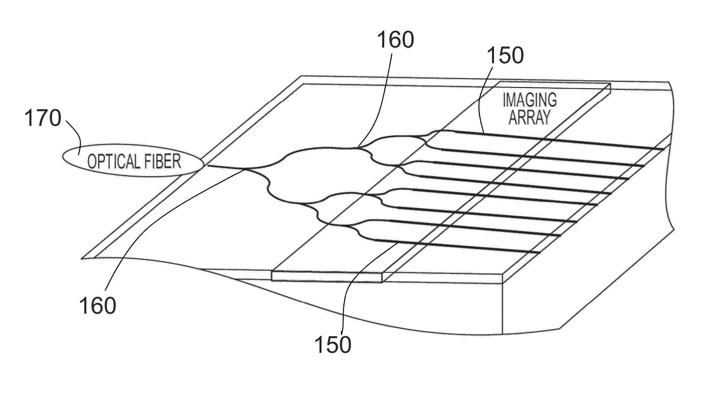
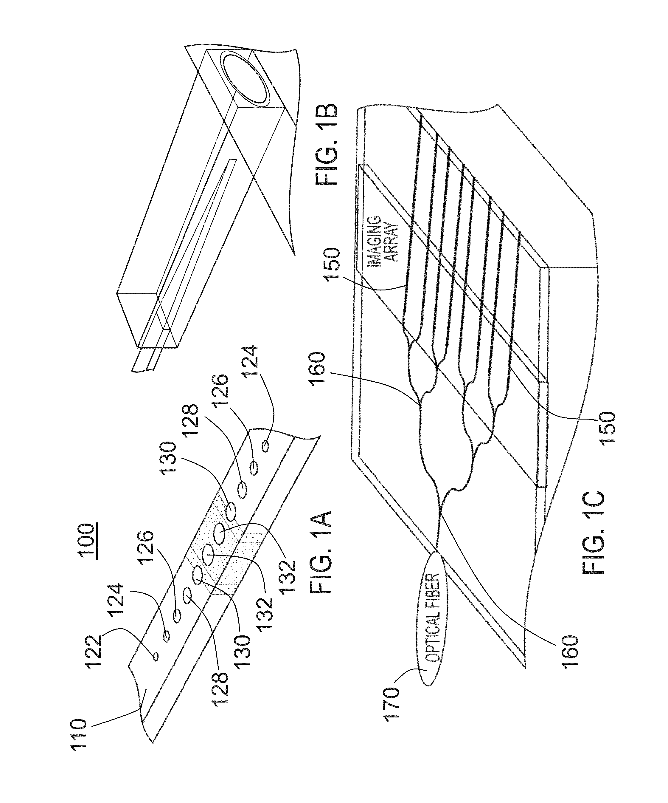
[0039]A mirror that provides a preferred Gaussian field distribution can be obtained by tapering conventional Bragg mirror by satisfying the following criteria. The periodicity of Bragg mirror is maintained—that is grating sections of the new mirror have constant periodicity. For example, if gratings are formed by etching holes along a waveguide, then the hole to hole distance are constant throughout the waveguide. Field distribution inside a conventional Bragg mirror goes as exp(−κx) where κ terms as mirror strength. The cavity design of the present invention, such as is shown in FIG. 1A, has a Gaussian field distribution exp(−σx2), which can be achieved by making the mirror strength of the conventional Bragg mirror dependent on the position within the grating as κ=σx. That is, the strength of grating section is increasing as a function of the distance from the center of the cavity. Such a mirror of the present invention may be referred to as a “modulated Bragg mirror”.

[0040]Archit...


PUM


Abstract

An on-chip integrated nanobeam cavity array spectrometer (INAS) having an array of waveguide-coupled nanobeam cavities. Waveguide splitters are used to bring the signal from the input waveguide into each cavity. The spectrum of unknown input signal is obtained by collecting signal from each nanobeam cavity in the array.

Description

CROSS-REFERENCE TO RELATED APPLICATIONS[0001]The present application is a national phase filing under 35 U.S.C. §371 of International Application No. PCT / US11 / 35695, filed May 9, 2011, entitled “Integrated Nanobeam Cavity Array Spectrometer”, which claims the benefit of the filing date of U.S. Provisional Application Ser. No. 61 / 332,266 entitled “Integrated Nanobeam Cavity Array Spectrometer” and filed on May 7, 2010.[0002]The above cross-referenced related application is hereby incorporated by reference herein in its entirety.STATEMENT REGARDING FEDERALLY SPONSORED RESEARCH OR DEVELOPMENT[0003]Not applicable.BACKGROUND OF THE INVENTION[0004]1. Field of the Invention[0005]The present invention relates to spectrometers and more particularly to a novel type of on-chip spectrometer that combines features of Fabry-Perot (FP) spectrometers with those of grating spectrometers.[0006]2. Brief Description of the Related Art[0007]Integrated optical spectrometers, in particular on-chip spectro...

Claims


Application Information

Patent Timeline
Patent Type & Authority Patents(United States)
IPC IPC(8): G01B9/02G01J3/26B82Y20/00G02B6/122G02B6/12
CPCG01J3/26B82Y20/00G02B6/1225G02B6/12011G02B2006/12069G02B2006/12097
Inventor LONCAR, MARKOQUAN, QIMINDEOTARE, PARAG B.
Owner PRESIDENT & FELLOWS OF HARVARD COLLEGE
Why Eureka
Try Eureka