Methods and apparatuses for structured illumination microscopy

a structured illumination and microscopy technology, applied in the field of structured illumination microscopy, can solve the problems of reducing the effective frame rate, difficult reconstruction of the result image, and fundamental limitations in the resolution power of the microscope, and achieves high signal-to-noise ratio, high excitation power, and high dynamic range

Active Publication Date: 2016-05-24
CARL ZEISS MICROSCOPY GMBH
View PDF18 Cites 2 Cited by
  • Summary
  • Abstract
  • Description
  • Claims
  • Application Information

AI Technical Summary

Benefits of technology

[0047]In particularly preferred embodiment forms of the methods according to the invention, the sample is excited by structured line illumination. This makes it possible to use high excitation powers.
[0048]In so doing, an intensity of the line illumination is advantageously adjusted in such a way that a dynamic range of a recording camera is fully utilized and the intensity is stored line by line. A high dynamic range means a high signal-to-noise ratio and, therefore, a high resolution.
[0049]The fluorescent light is preferably detected confocally, particularly by means of a laser scanning microscope. In this way, out-of-focus light is efficiently discriminated and the signal-to-noise ratio is accordingly improved. By combining confocal detection with structured line illumination, background which may possibly be disruptive for the feedback is reduced already during image recording.

Problems solved by technology

Since the usable wavelength range of visible light is finite, the resolving power of a microscope is fundamentally limited (Abbe, 1873).
Further, the required multiple recording reduces the effective frame rate.
As a result, distinctly different nonlinearities may be achieved at different locations in the sample, which makes reconstruction of the result image more difficult.
In some cases, the environmental conditions in the sample can be so unfavorable for a nonlinear interaction that the use of SPEM is impossible.
In SIM and SPEM, the resolution which can be achieved by reconstruction is fundamentally limited by the signal-to-noise ratio (SNR) in the recording of individual images.

Method used


Image

  • Methods and apparatuses for structured illumination microscopy
  • Methods and apparatuses for structured illumination microscopy
  • Methods and apparatuses for structured illumination microscopy

Examples


Embodiment Construction

[0058]It is to be understood that the figures and descriptions of the present invention have been simplified to illustrate elements that are relevant for a clear understanding of the present invention, while eliminating, for purposes of clarity, many other elements which are conventional in this art. Those of ordinary skill in the art will recognize that other elements are desirable for implementing the present invention. However, because such elements are well known in the art, and because they do not facilitate a better understanding of the present invention, a discussion of such elements is not provided herein.

[0059]The present invention will now be described in detail on the basis of exemplary embodiments.

[0060]Identical parts have identical reference numerals in all of the drawings.

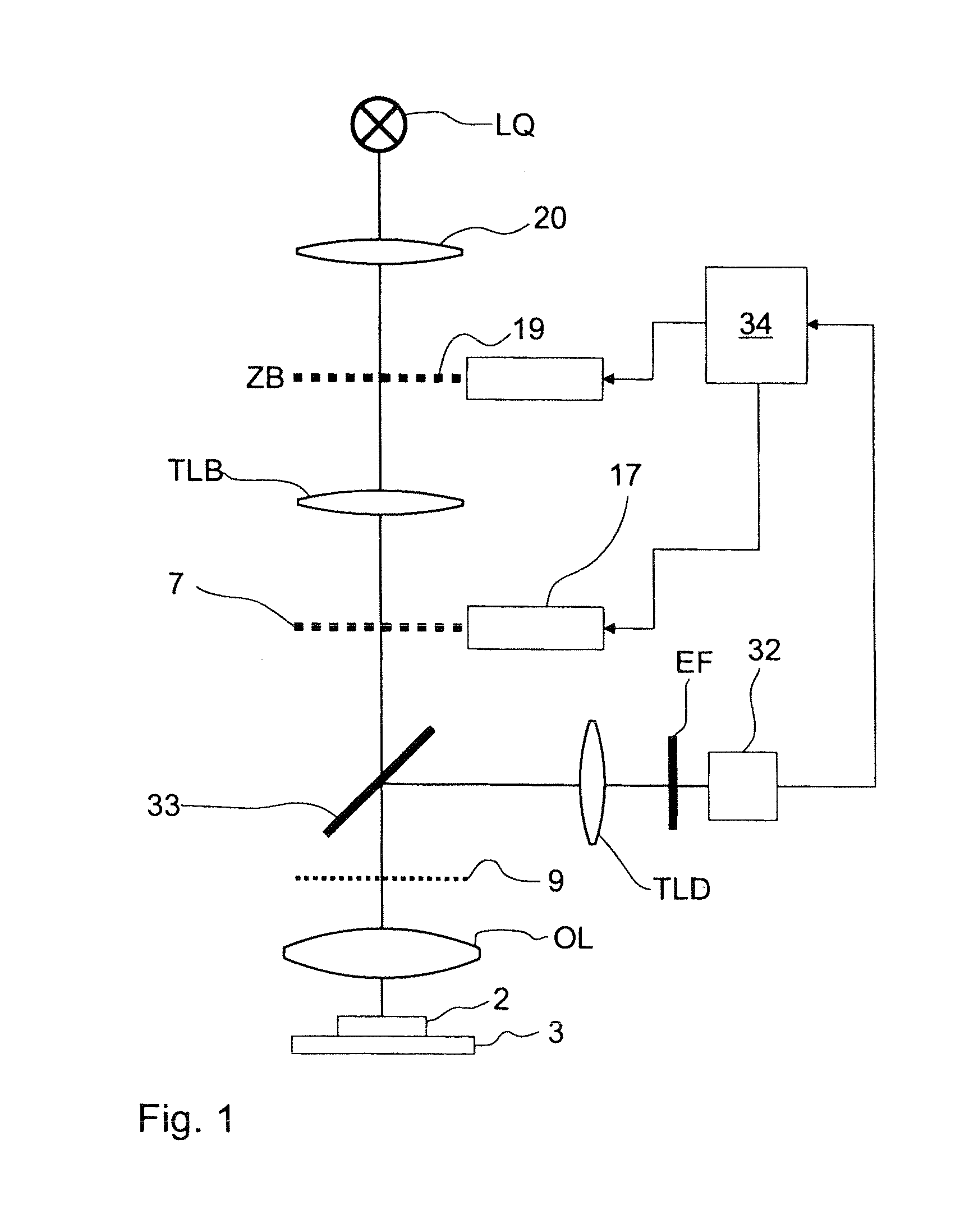
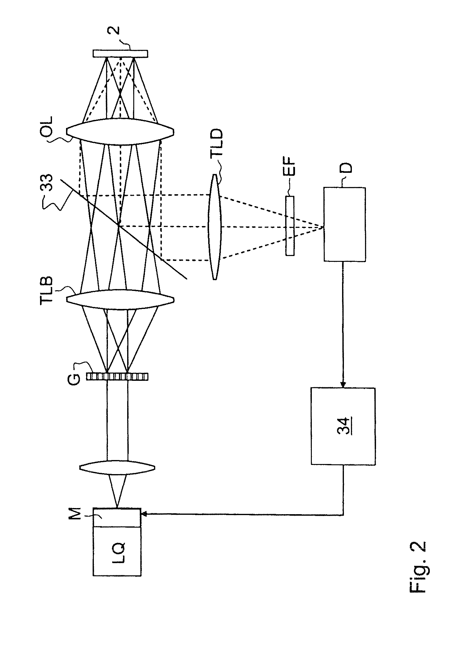
[0061]FIG. 1 shows a schematic view of the beam path of an arrangement for widefield fluorescence microscopy serving by way of example, in which the SIM and SPEM methods which are improved by the inv...


PUM

PropertyMeasurementUnit
sizeaaaaaaaaaa
sizeaaaaaaaaaa
thicknessaaaaaaaaaa

Abstract

In structured illumination microscopy, the multiple recording of images with different phase positions of the structuring requires a high stability in the optical arrangement and sample throughout the entire measuring process. Also, the structuring must be projected into the sample in a highly homogeneous manner. The current invention optimizes recording of individual images in order to achieve the best possible resolution in the result image even in problematic samples. An optimization of this kind can be carried out in different ways, for example, by determining an optimal adjustment for at least one illumination parameter or recording parameter or by pulsed illumination such that an excitation from a triplet state of the fluorescent dye to a higher triplet state is reduced, or by illuminating the sample with depletion light for depopulating a triplet state of the fluorescent dye, which reduces bleaching.

Description

[0001]The present application claims priority from PCT Patent Application No. PCT / EP2009 / 006818 filed on Sep. 22, 2009, which claims priority from German Patent Application No. DE 10 2008 049 878.5 filed on Sep. 30, 2008, the disclosure of which is incorporated herein by reference in its entirety.BACKGROUND OF THE INVENTION[0002]1. Field of the Invention[0003]The invention is directed to methods and devices for high-resolution microscopic imaging of a sample labeled with a fluorescent dye, wherein the sample is illuminated sequentially in a plurality of phases by structured, pulsed excitation light, and the fluorescent light emitted by the sample is recorded for each phase in a respective structured individual image so that a result image with enhanced resolution can be reconstructed from the individual images.[0004]2. Description of Related Art[0005]Due to the fact that the light received from the sample is diffracted in the microscope objective, the resolving power of microscopes ...

Claims


Application Information

Patent Timeline
Patent Type & Authority Patents(United States)
IPC IPC(8): G06K9/40G02B21/00G01N21/64G02B21/36G02B27/58
CPCG02B21/0032G01N21/6458G02B21/0076G02B21/367G02B27/58G02B21/008G02B21/0072
Inventor KEMPE, MICHAELKRAMPERT, GERHARDKLEPPE, INGOWOLLESCHENSKY, RALF
Owner CARL ZEISS MICROSCOPY GMBH
Why Eureka
Try Eureka