Digital-to-analog converter with local interleaving and resampling

a digital-to-analog converter and local interleaving technology, applied in the field of digital-to-analog converters, can solve the problems of time glitches between analog equivalent output cells within the dac, poor accuracy of the fastest conversion method, and inability to meet the requirements of time-consuming and laborious, so as to reduce design constraints

Active Publication Date: 2016-05-24
ROHDE & SCHWARZ GMBH & CO KG
View PDF12 Cites 7 Cited by
  • Summary
  • Abstract
  • Description
  • Claims
  • Application Information

AI Technical Summary

Benefits of technology

[0039]Preferably, a means of interleaving two half rate sub-DAC codes at the data inputs are provided. At higher frequencies, combining slower rate input sub-DACs reduces design constraints as only the final analog switch is required to operate at the full data rate.
[0040]Preferably, a topology that enables final retiming in the analog output switch circuit is provided. Retiming in the final analog circuit gives the best possible phase noise performance, compare to all other possible DAC topologies.

Problems solved by technology

Due to the complexity and the need for precisely matched components, DACs are mostly implemented as integrated circuits, short IC.
This is one of the fastest conversion methods but suffers from poor accuracy, because of the high precision required for each individual voltage or current and the needed time-alignment of the individual parallel components.
Digital sampling introduces quantization error that manifests as low-level noise added to the reconstructed signal.
For those DACs with sampling rates of tens of gigahertz, time glitches between the equivalent analog output cells within the DAC becomes a critical challenge to the DAC design.
A drawback of such a structured analog output cell is that the output signal of the analog output cell is a return-to-zero signal, short RZ signal.
This structure leads to the disadvantage that the effective RF output power is effectively cut in half, since the signal output is set to zero for half of the time.
Additionally, no mixed-mode of the analog output cell can be obtained since the clock transistors are arranged at the analog output cell.
Another drawback of such a structure is the fact that the data switching occurs before the retiming switching.
This leads to additional distortion on the signaling path.

Method used


Image

  • Digital-to-analog converter with local interleaving and resampling
  • Digital-to-analog converter with local interleaving and resampling
  • Digital-to-analog converter with local interleaving and resampling

Examples


Embodiment Construction

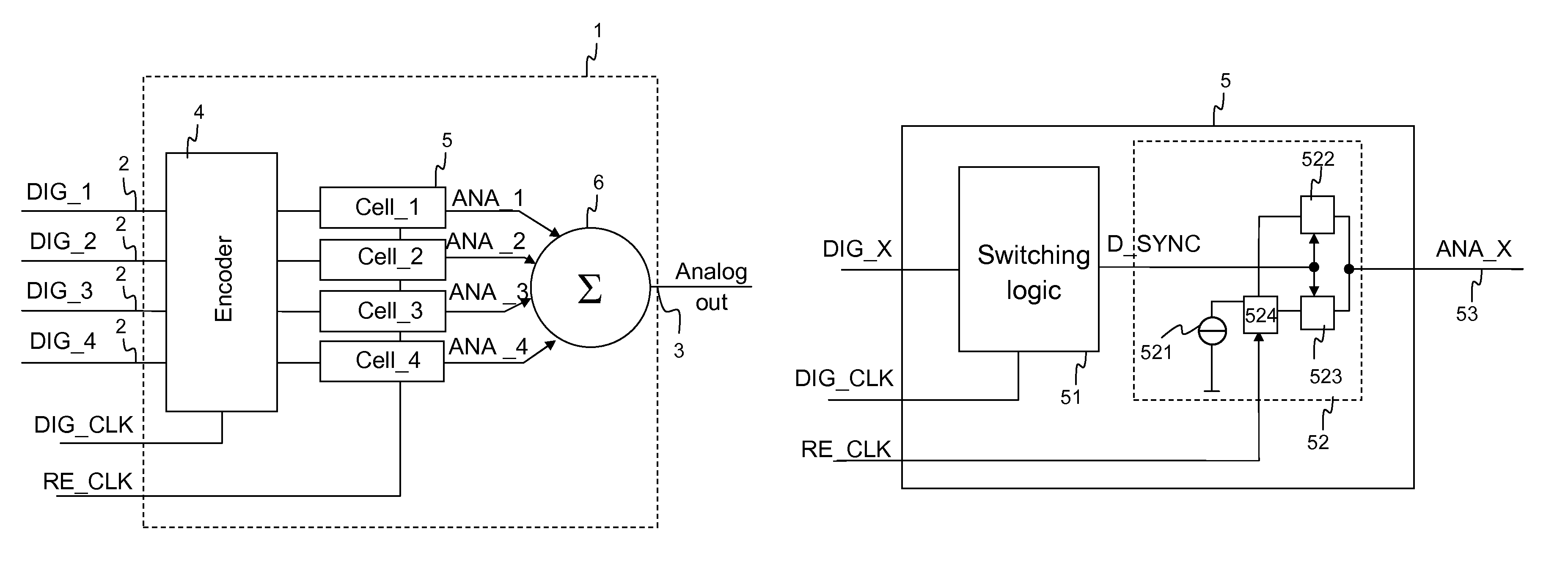
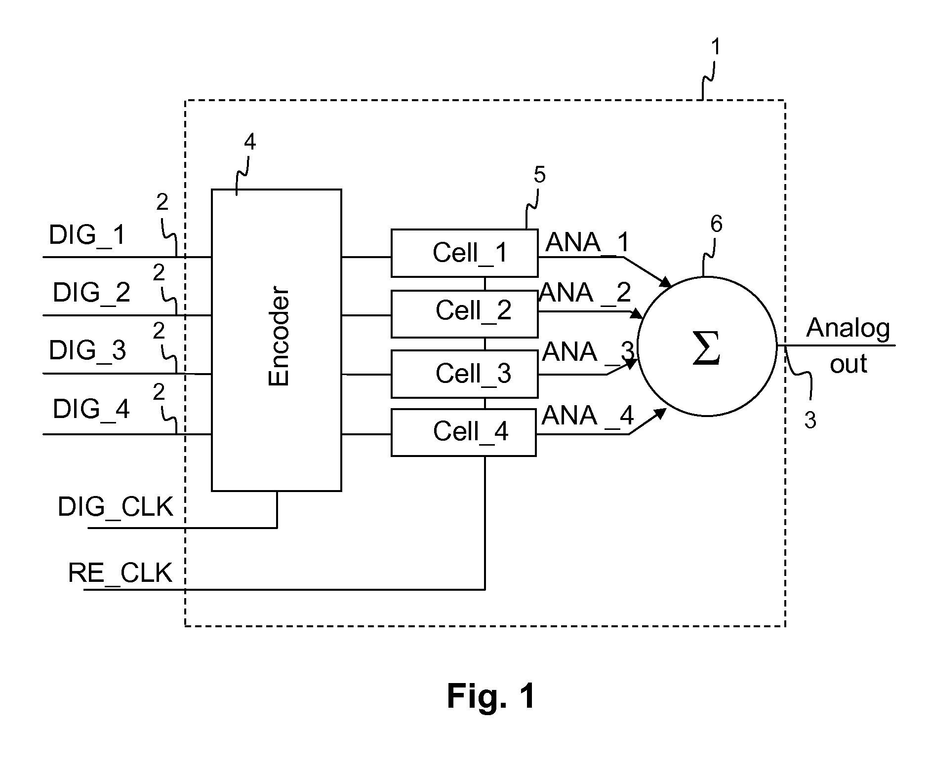
[0056]FIG. 1 shows a first exemplary embodiment of a DAC_1 according to the invention. The DAC_1 comprises a plurality of digital input ports 2. At the digital input ports 2, a plurality of digital input signals is applied. For reasons of simplicity, only four digital input signals DIG_1, DIG_2, DIG_3 and DIG_4 are shown. Each of the digital input signals DIG_1, DIG_2, DIG_3 und DIG_4 are binary rated and provided to an encoder unit 4. Downstream to the encoder unit 4 four analog output cells 5 are arranged to selectively generate partial analog signals ANA_1, ANA_2, ANA_3 and Ana_4 in response to the digital input signals DIG_1, DIG_2, DIG_3 and DIG_4. The analog output signals ANA_1, ANA_2, ANA_3 and Ana_4 are provided to a summing unit 6. In the summing unit 6 the partial analog signal ANA_1, ANA_2, ANA_3 and ANA_4 are summed to obtain the analog output signal analog_out at the analog output port 3 of the DAC_1.

[0057]The encoder unit 4 of the DAC_1 operates to translate the four ...


PUM


Abstract

The invention relates to a digital to analog converter and a method for a digital to analog conversion, wherein the digital to analog converter comprises at least one analog output cell configured to selectively generate a partial analog signal in response to a partial digital input signal. The analog output cell comprises an analog output switching unit that comprises a current source connected in series to a first node of a retiming switch and a first switch element as well as a second switching element, both connected with respect to first nodes in parallel to a second node of the retiming switch and a switching logic configured to regulate the transmission of said partial analog signal to an analog cell output.

Description

TECHNICAL FIELD OF THE INVENTION[0001]The invention relates to digital-to-analog converters, short DAC, for converting a digital input signal into an analog signal. The invention further relates to a method for a digital-to-analog conversion.[0002]Nowadays, high speed, high dynamic range, DACs are key to radio frequency, short RF, signal generation for wireless and wireline networks, digital terrestrial television, cellular communication, software defined radio, radar as well as test- and measurement-applications.[0003]The use of high speed, high dynamic range DACs allows for direct digital synthesis without intermediate analog circuit functions, such as mixers, resulting in fewer mixing products, fewer spurious signals and reduced signal distortion. These DACs enable new signal synthesis applications in test equipments, especially when RF signals require accurate harmonic generation up to higher orders, such as fifth harmonic and beyond.BACKGROUND OF THE INVENTION[0004]There are se...

Claims


Application Information

Patent Timeline
Patent Type & Authority Patents(United States)
IPC IPC(8): H03M1/66H03M1/76H03M1/70
CPCH03M1/76H03M1/662H03M1/70H03M1/0863H03M1/68H03M1/0624H03M1/1215H03M1/0872H03M1/742
Inventor FETCHE, RADUJUNG, FAYELEHNE, MARK
Owner ROHDE & SCHWARZ GMBH & CO KG
Why Eureka
Try Eureka