Bonded composite airfoil

a composite airfoil and bonding technology, applied in the field of airfoils, can solve the problems of reducing airfoil performance, reducing airfoil quality, and reducing airfoil performance, so as to reduce product inconsistencies, reduce parts count, and reduce the effect of complexity and weigh

Active Publication Date: 2016-05-31
THE BOEING CO
View PDF20 Cites 11 Cited by
  • Summary
  • Abstract
  • Description
  • Claims
  • Application Information

AI Technical Summary

Benefits of technology

[0006]The disclosed embodiments provide an airfoil, such as an airplane wing box or control surface, and a related fabrication method that allows precured composite sandwich panel skins to be adhesively bonded to precured composite sandwich spars in a secondary bonding operation, thereby reducing or obviating the need for fastened joints between the skins and the spars. Use of composite sandwich panel skins and spars provides the airfoil with the required stiffness while reducing part count, complexity and weight. Precuring the wing skins and wing spars separately in an autoclave before the secondary bonding operation may reduce product inconsistencies, improve the quality of the airfoil, simplify production processes and reduce manufacturing flow time. Load transfer through the skin-to-spar bonds may be reduced by integrating the spar caps into the spars, and by employing spar caps that are reinforced laminates. The spar caps are substantially aligned with the composite sandwich panel skins. Spar weight is minimized by employing spar webs that are of a honeycomb sandwich construction. Use of composite sandwich panel skins may reduce or eliminate the needs for longitudinal wing stringers, while reducing the number of, or spacing between wing ribs.

Problems solved by technology

However, the use of fastener joints may present difficulties in composite spar wing and control surface designs, in part because composites may have a lower bearing capacity than metals.
The need to add reinforcements in the wing may reduce airfoil performance, add undesired weight to the aircraft and / or increase manufacturing costs.

Method used


Image

  • Bonded composite airfoil
  • Bonded composite airfoil
  • Bonded composite airfoil

Examples


Embodiment Construction

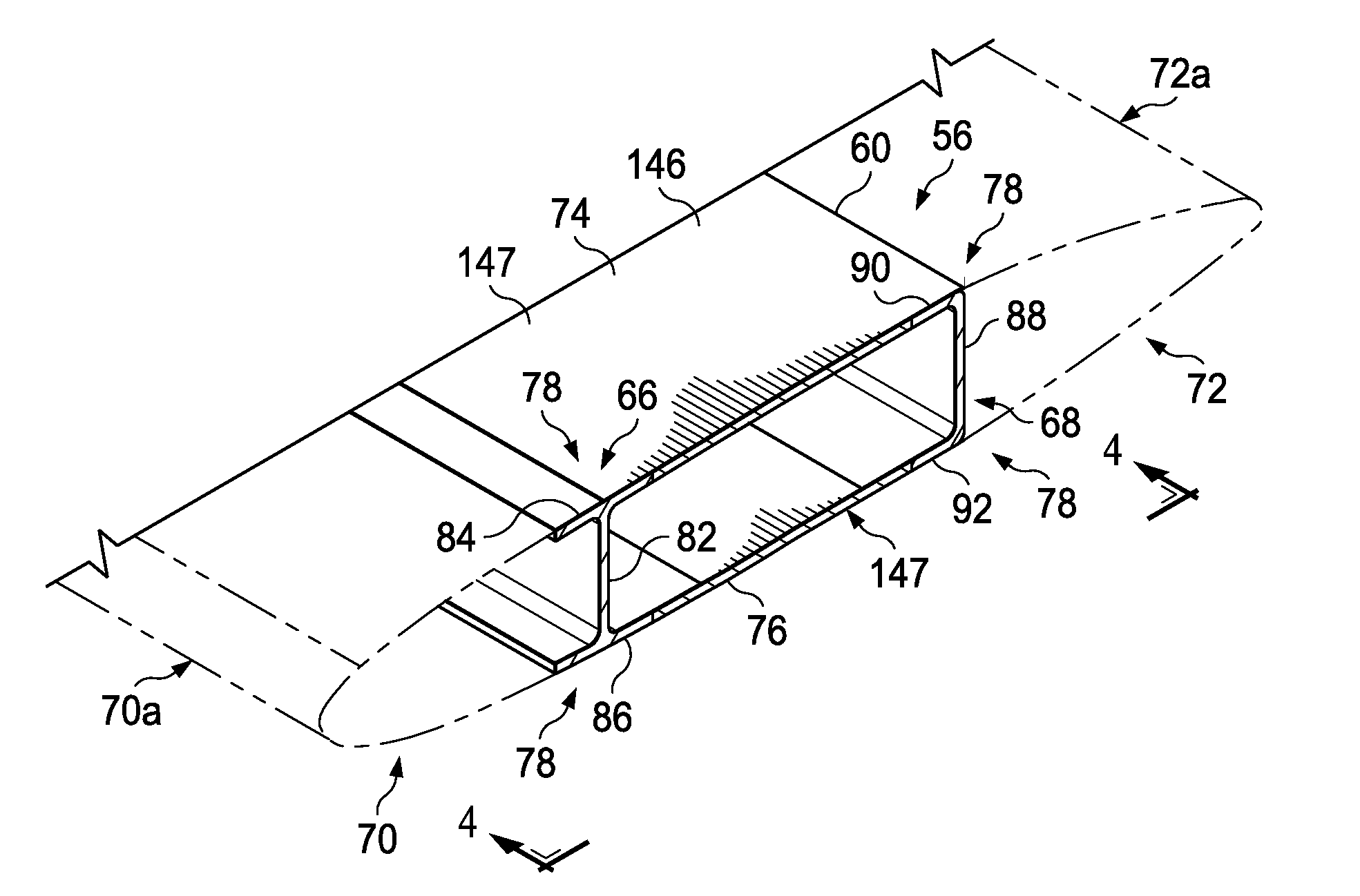
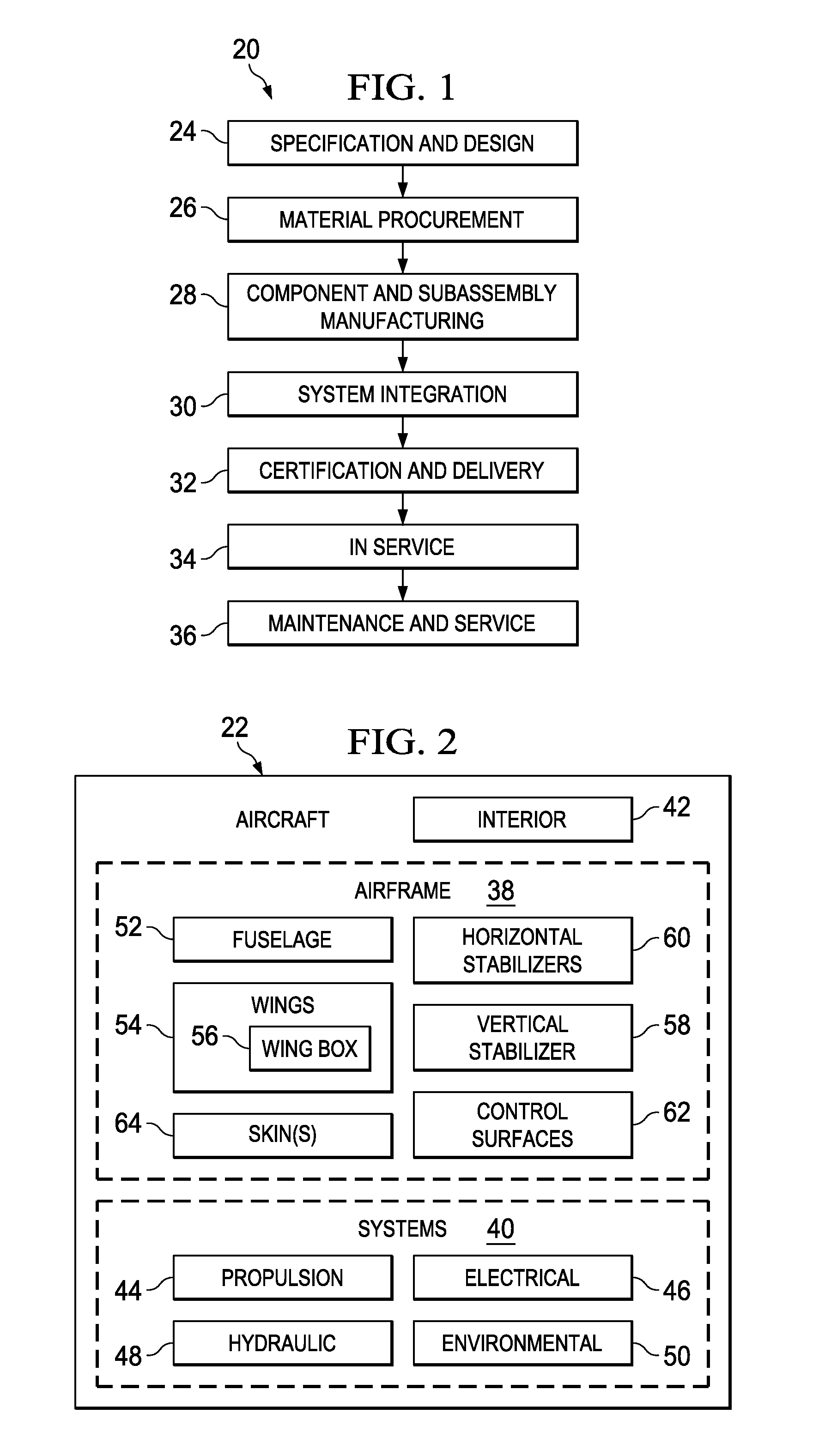
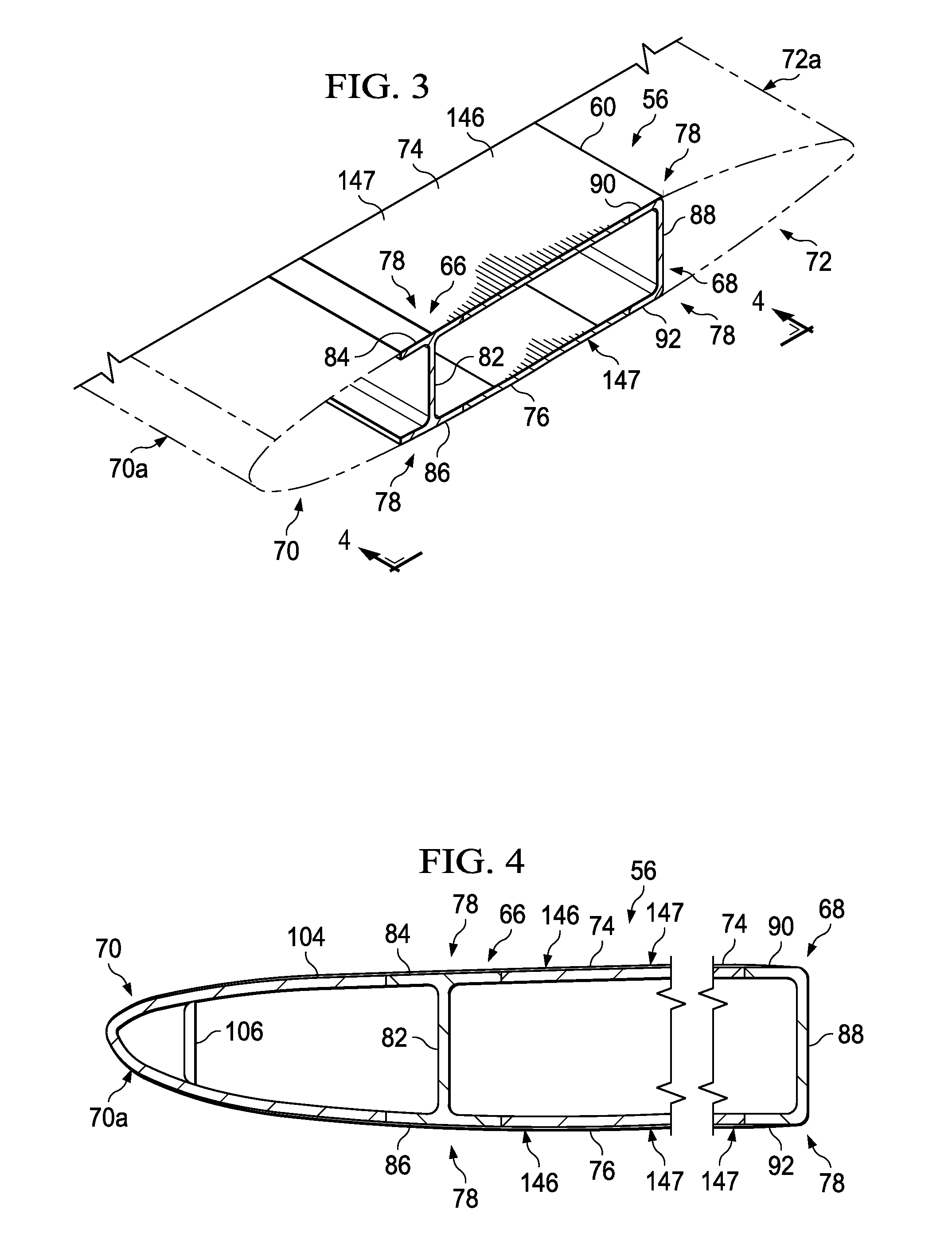
[0025]The disclosed embodiments involve a bonded composite airfoil and a related fabrication method. The embodiments may find use in a variety of potential applications, particularly in the transportation industry, including for example, aerospace, marine, automotive applications and other applications where light weight airfoil-like structures are employed. Thus, referring now to FIGS. 1 and 2, embodiments of the disclosure may be used in the context of an aircraft manufacturing and service method 20 as shown in FIG. 1 and an aircraft 22 as shown in FIG. 2. Aircraft applications of the disclosed embodiments may include, for example, without limitation, wings 54, a vertical stabilizer 58 and horizontal stabilizers 60 forming part of the airframe 38, to name only a few. During pre-production, exemplary method 20 may include specification and design 24 of the aircraft 22 and material procurement 26. During production, component and subassembly manufacturing 28 and system integration 3...


PUM

PropertyMeasurementUnit
densityaaaaaaaaaa
shapeaaaaaaaaaa
bearing capacityaaaaaaaaaa

Abstract

An airfoil includes at least one precured composite spar having a web and at least one flange integrated with an end of the web. A precured composite skin is attached to the spar by adhesive bonding the skin to the flange.

Description

BACKGROUND INFORMATION[0001]1. Field[0002]The present disclosure generally relates to airfoils, such as a wing box for an aircraft, and deals more particularly with an airfoil construction having a composite outer skin bonded to wing spars.[0003]2. Background[0004]Aircraft wings and / or control surfaces may employ a framework of spars, ribs and stringers that are covered with an outer skin. The spars may carry a majority of the wing load while the ribs both stiffen the wing and provide an airfoil shape for the wing skin. In the case of metal wing constructions, metal structures may be attached to the metal spars using fastener joints. However, the use of fastener joints may present difficulties in composite spar wing and control surface designs, in part because composites may have a lower bearing capacity than metals. Accordingly, composite wing constructions using fasteners may require reinforcements to increase their fastener bearing capacity in joint areas. The need to add reinfor...

Claims


Application Information

Patent Timeline
Patent Type & Authority Patents(United States)
IPC IPC(8): B64C3/20B64C3/26B29C65/48B29C65/00B29L31/30
CPCB64C3/20B29C65/483B29C66/1162B29C66/1282B29C66/1284B29C66/1286B29C66/12821B29C66/524B29C66/543B29C66/723B29C66/72141B29C66/72525B29C66/73756B64C3/26B29C65/4835B29L2031/3085Y10T156/10Y02T50/40B29C70/04B64C3/18
Inventor NORDMAN, PAUL STANLEY
Owner THE BOEING CO
Why Eureka
Try Eureka