
Plasma processing apparatus

a processing apparatus and plasma technology, applied in the direction of plasma technique, coating, electric discharge lamps, etc., can solve the problems of difficult control of etching depth and charge damage on gate oxide films, and achieve the effect of suppressing the rf power trailing phenomenon, simple and securely

Active Publication Date: 2016-05-31
TOKYO ELECTRON LTD +1
View PDF26 Cites 36 Cited by
  • Summary
  • Abstract
  • Description
  • Claims
  • Application Information

AI Technical Summary

Benefits of technology

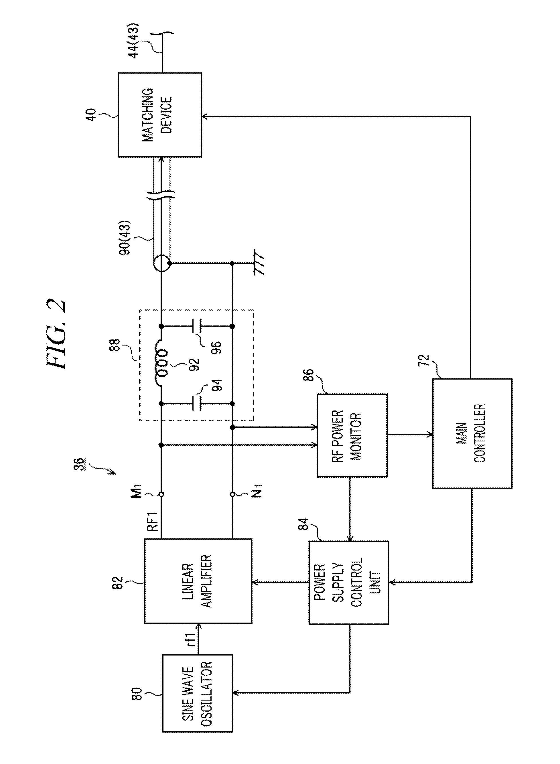
The plasma processing apparatus described in this patent prevents a phenomenon called RF power trailing during power modulation on a switching high frequency power supply. This means that the apparatus can operate more efficiently and safely.

Problems solved by technology

However, if the ion energy is lowered at a lower pressure, the non-uniformity of the plasma potential in the entire surface of the substrate may easily cause the charging damage on a gate oxide film.
That is, an etching rate may differ depending on the hole size, so that it is difficult to control an etching depth.

Method used


Image

  • Plasma processing apparatus
  • Plasma processing apparatus
  • Plasma processing apparatus

Examples


example embodiment or modification example

Another Example Embodiment or Modification Example

[0082]The example embodiment has been explained, but is not limited thereto, and can be modified in various ways within a technical scope thereof.

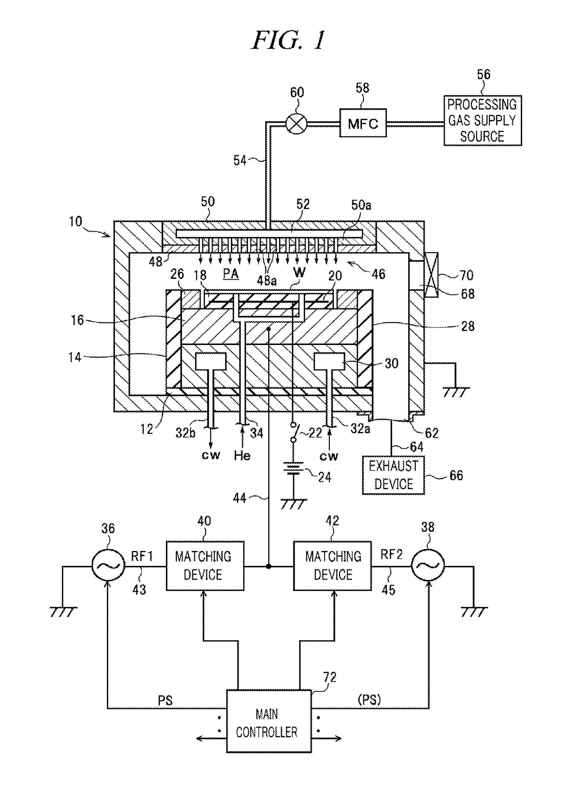
[0083]In the above example embodiment, the switching type high frequency power supply is used as the second high frequency power supply 38, and the residual high frequency power removing unit 74 is provided on the high frequency power supply line 45. However, the switching type high frequency power supply may be used as the first high frequency power supply 36, and in this case, another residual high frequency power removing unit 74 may be provided on the high frequency power supply line 43.

[0084]Further, the switching type high frequency power supply may be used as both of the first high frequency power supply 36 and the second high frequency power supply 38. In this case, the residual high frequency power removing unit 74 may be provided on each of the high frequency power supply line 43 ...


PUM

PropertyMeasurementUnit
frequencyaaaaaaaaaa
frequencyaaaaaaaaaa
frequency f1aaaaaaaaaa

Abstract

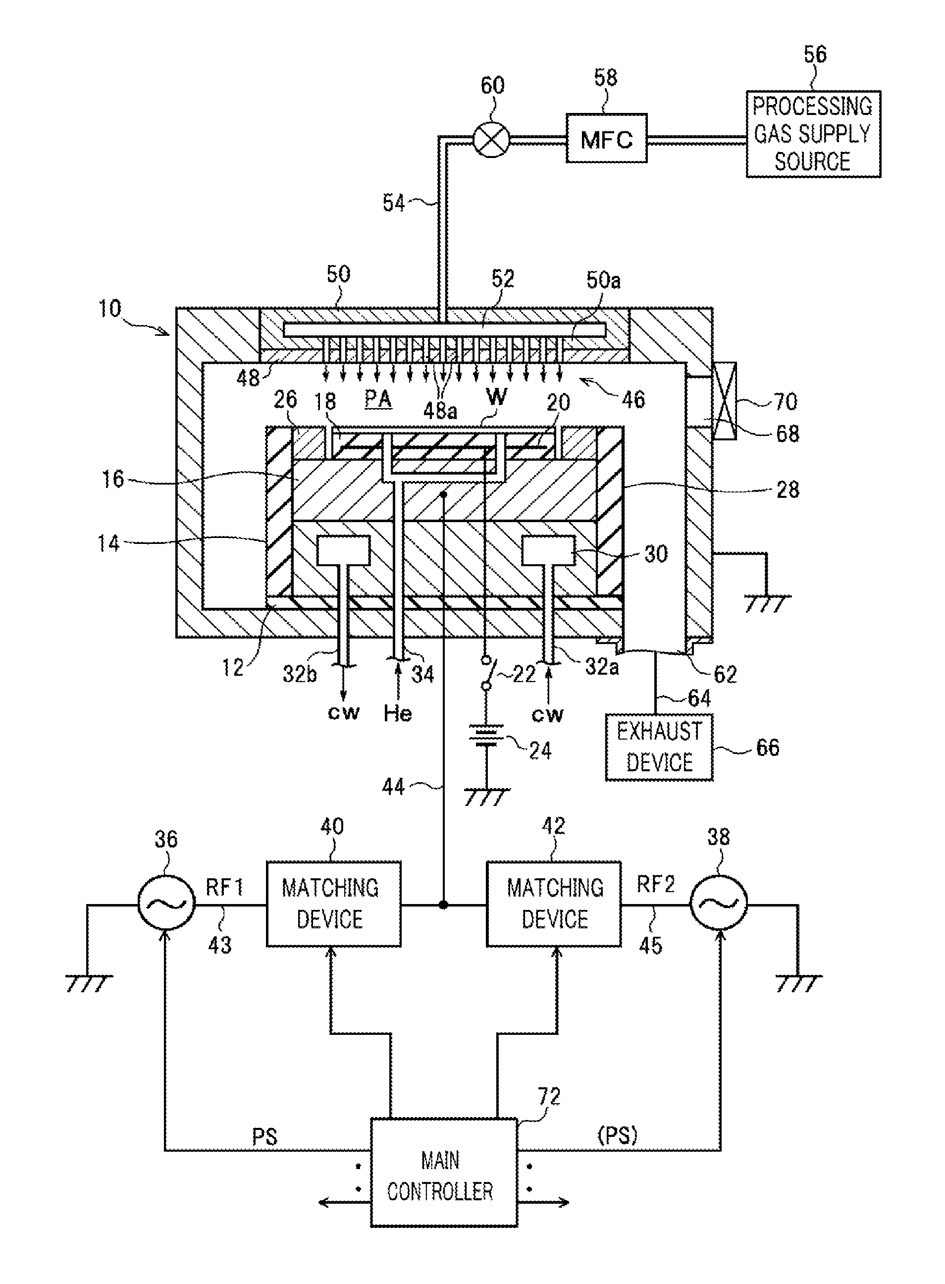
In a capacitively coupled plasma processing apparatus, a susceptor (lower electrode) 16 within a decompression chamber 10 faces an upper electrode 46 serving as a shower head. The susceptor 16 is electrically connected with a first high frequency power supply 36 and a second high frequency power supply 38 via matching devices 40 and 42, respectively. The first high frequency power supply 36 is formed of a linear amplifier type high frequency power supply and outputs a first high frequency power RF1 for plasma generation. The second high frequency power supply 38 is formed of a switching type high frequency power supply and outputs a second high frequency power RF2 for ion attraction. A residual high frequency power removing unit 74 is connected to a high frequency power supply line 45 on a side of the second high frequency power supply 38.

Description

CROSS-REFERENCE TO RELATED APPLICATION[0001]This Application is a U.S. national phase application under 35 U.S.C. §371 of PCT Application No. PCT / JP2012 / 007975 filed on Dec. 13, 2012, which claims the benefit of Japanese Patent Application No. 2011-286024 filed on Dec. 27, 2011, and U.S. Provisional Application Ser. No. 61 / 585,734 filed on Jan. 12, 2012, the entire disclosures of which are incorporated herein by reference.TECHNICAL FIELD[0002]The embodiments described herein pertain generally to a technology of performing a plasma process on a processing target substrate, and more particularly, pertain to a capacitively coupled plasma processing apparatus in which a high frequency power for plasma generation is modulated in a pulse shape.BACKGROUND[0003]A capacitively coupled plasma processing apparatus includes an upper electrode and a lower electrode arranged in parallel to each other within a processing vessel. A processing target substrate (e.g., a semiconductor wafer, a glass s...

Claims


Application Information

Patent Timeline
Patent Type & Authority Patents(United States)
IPC IPC(8): H01J7/24C23C16/509H01J37/32C23C16/515H05H1/46
CPCH01J37/32155C23C16/5096C23C16/515H01J37/32091H01J37/32165H01J37/32174H01J37/32183H05H2001/4682H05H2242/26
Inventor YAMADA, NORIKAZUTACHIKAWA, TOSHIFUMINAGAMI, KOICHIIKENARI, TATSUYAMAEHARA, DAISUKE
Owner TOKYO ELECTRON LTD
Learn More