Catheter pump

a catheter pump and catheter technology, applied in blood pumps, prostheses, medical science, etc., can solve the problems of high mortality rate, increased stress on heart failure patients, and inability to advance percutaneously, and achieve the effect of minimizing the risk of fracture within the mesh and facilitating compression

Active Publication Date: 2016-06-07
THORATEC CORPORTION
View PDF493 Cites 65 Cited by
  • Summary
  • Abstract
  • Description
  • Claims
  • Application Information

AI Technical Summary

Benefits of technology

[0011]In some embodiments, the cannula is differentiated along its length to have varying stiffness. The elongate cannula has an impeller zone disposed about the impeller and a distal zone disposed distal of the impeller zone. The distal zone can be made more flexible by reducing the number of connectors disposed therein. For example, the impeller zone can have alternating elongate struts that are connected by circumferential connectors and the distal zone can have alternating elongate struts that are free of such connections.
[0015]In some configurations, the elongate cannula has an impeller zone disposed about the impeller and a distal zone disposed distal of the impeller zone. For example, the impeller can extend in about one-half or less of the length of the cannula. The distal zone may be more easily compressed by the sheath because the impeller is not present in that area. As a result, the cannula can have a different configuration in the distal zone.
[0016]In another configuration, a catheter pump is provided. A catheter pump is an example of an apparatus for inducing motion of a fluid relative to the apparatus. The catheter pump includes a rotatable impeller and an elongate cannula having a mesh comprising a plurality of circumferential members disposed about the impeller. The mesh also has a plurality of axial connectors extending between a proximal side of a distal circumferential member and a distal side of a proximal circumferential member. The circumferential members are radially self-expandable. A sheath is configured to be positioned over the elongated cannula to actuate the cannula from an expanded configuration to a collapsed configuration. The cannula is configured to minimize a risk of fracture within the mesh, e.g., of the axial connectors, as the elongated cannula moves into the sheath.
[0019]In another embodiment, a catheter pump is provided that includes a rotatable impeller and an elongate cannula. The elongate cannula has a mesh that has a plurality of circumferential members disposed about the impeller. The elongate cannula has a plurality of axial connector extending between a proximal side of a distal circumferential member and a distal side of a proximal circumferential member. The circumferential members are radially self-expandable. The cannula is configured to minimize fracture within at least in the distal zone of the mesh as the elongated cannula moves into a sheathing device.

Problems solved by technology

Heart disease is a major health problem that has high mortality rate.
Surgical insertion, however, can cause additional serious stresses in heart failure patients.
Conventional fixed cross-section ventricular assist devices designed to provide near full heart flow rate are too large to be advanced percutaneously, e.g., through the femoral artery.
Broken struts pose a risk of complicating patient treatment and / or compromising the performance of the device.

Method used


Image

  • Catheter pump
  • Catheter pump
  • Catheter pump

Examples


Embodiment Construction

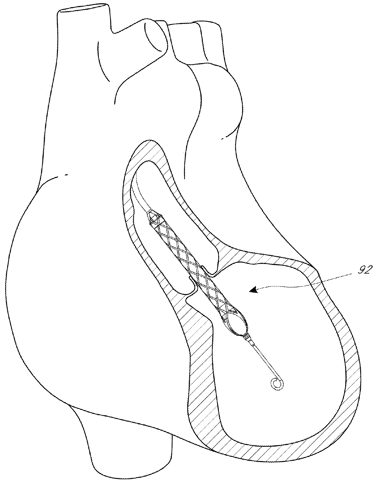
[0048]This application is directed to apparatuses for inducing motion of a fluid relative to the apparatus. The apparatus can be a catheter pump, e.g., a percutaneous heart pump.

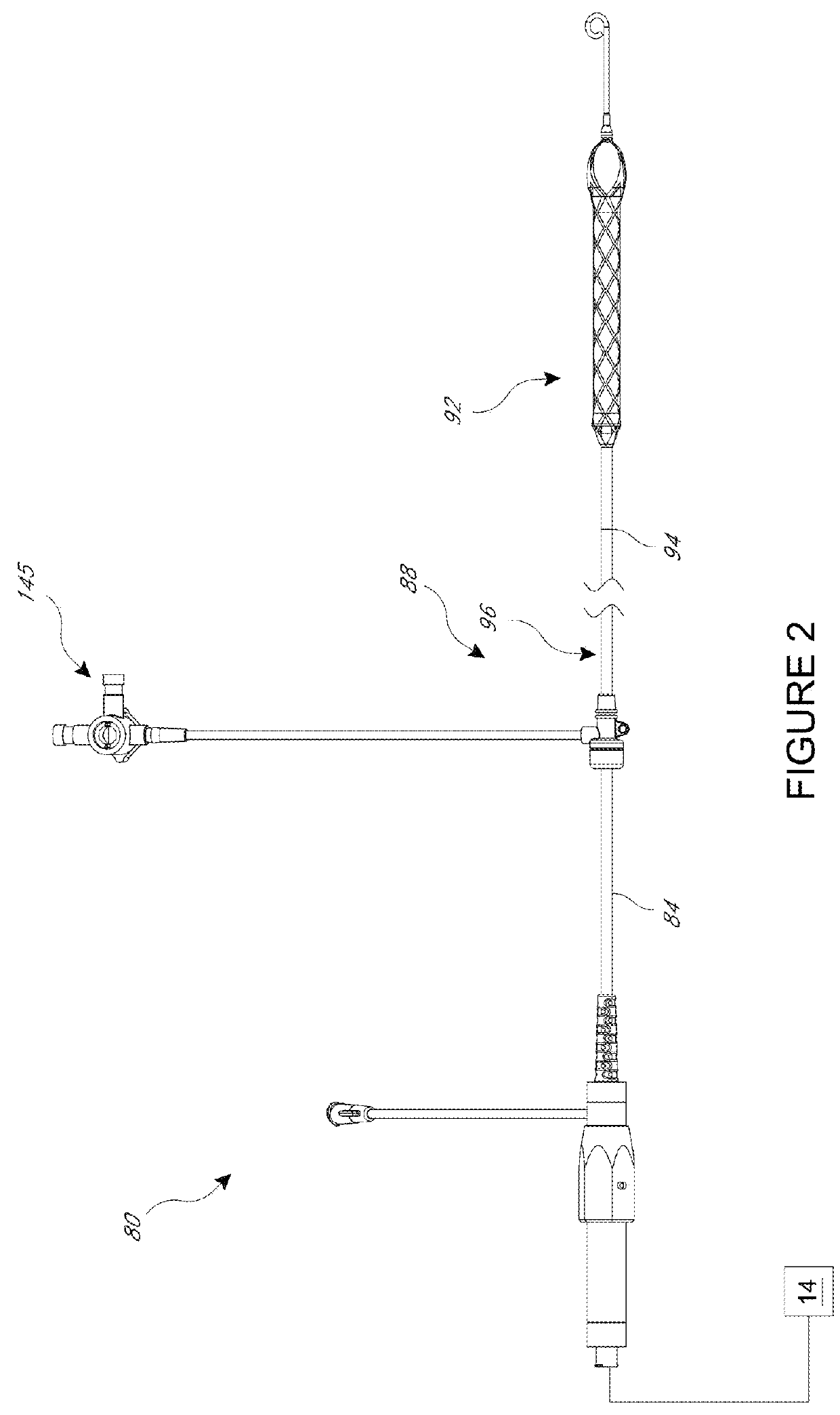
[0049]FIGS. 1 and 2 illustrate various features of a catheter pump 10. The catheter pump 10 can provide high performance including flow rates similar to full cardiac output. The pump 10 includes a motor driven by a controller 22. The controller 22 directs the operation of the motor 14 and an infusion system 26 that supplies a flow of infusate in the pump 10. A catheter system 80 that can be coupled with the motor 14 houses an impeller within a distal portion thereof. In various embodiments, the impeller is rotated remotely by the motor 14 when the pump 10 is operating. For example, the motor 14 can be disposed outside the patient. In some embodiments, the motor 14 is separate from the controller 22, e.g., to be placed closer to the patient. In other embodiments, the motor 14 is part of the controller 22. In ...


PUM


Abstract

A catheter pump is provided that includes a rotatable impeller and an elongate cannula. The elongate cannula has a mesh that has a plurality of circumferential members disposed about the impeller. The elongate cannula has a plurality of axial connector extending between a proximal side of a distal circumferential member and a distal side of a proximal circumferential member. The circumferential members are radially self-expandable. The cannula is configured to minimize fracture within at least in the distal zone of the mesh as the elongated cannula moves into a sheathing device.

Description

INCORPORATION BY REFERENCE TO ANY PRIORITY APPLICATIONS[0001]Any and all applications for which a foreign or domestic priority claim is identified in the Application Data Sheet as filed with the present application, including U.S. Application No. 61 / 667,903 filed Jul. 3, 2012 entitled Catheter Pump, are hereby incorporated by reference under 37 CFR 1.57.BACKGROUND OF THE INVENTION[0002]1. Field of the Invention[0003]This application is directed to a catheter pump for mechanical circulatory support of a heart.[0004]2. Description of the Related Art[0005]Heart disease is a major health problem that has high mortality rate. After a heart attack, only a small number of patients can be treated with medicines or other non-invasive treatment. However, a significant number of patients can recover from a heart attack or cardiogenic shock if provided with mechanical circulatory support.[0006]In a conventional approach, a blood pump having a fixed cross-section is surgically inserted between t...

Claims


Application Information

Patent Timeline
Patent Type & Authority Patents(United States)
IPC IPC(8): A61N1/362A61M1/10A61M1/12A61M60/13A61M60/174A61M60/216A61M60/411A61M60/508A61M60/81A61M60/825A61M60/857
CPCA61M1/101A61M1/1008A61M1/10A61M1/12A61M1/122A61M60/857A61M60/414A61M60/13A61M60/237A61M60/808A61M60/81A61M60/859A61M60/411A61M60/174A61M60/216A61M60/508A61M60/825A61M60/148
Inventor FITZGERALD, KEIF M.KEENAN, RICHARD L.HARRISON, WILLIAM J.
Owner THORATEC CORPORTION
Why Eureka
Try Eureka