Micromachined mass flow sensor with condensation prevention and method of making the same

a mass flow sensor and micromachined technology, applied in the field of micromachined silicon sensors, can solve the problems of affecting the flow readout, clogging of additional liquid condensation, and not changing the basic performance of the so as to maximize the sensitivity of the said silicon mass flow sensor, save the energy necessary for operation, and accurately measure the

Active Publication Date: 2016-06-07
WISENSTECH
View PDF4 Cites 3 Cited by
  • Summary
  • Abstract
  • Description
  • Claims
  • Application Information

AI Technical Summary

Benefits of technology

[0006]It is the objective of this invention to provide the design and process of a silicon gas mass flow sensor that shall have the capability of nonstop performing when measuring a flow medium with heavy presence of humidity or water droplets or other liquid vapors. In addition, the said silicon mass flow sensor can from time to time self-check and provide information timely via the interface. Further this invention disclosed the detailed process for the said silicon mass flow sensor.
[0010]In another preferred embodiment, the invented silicon mass flow sensor shall have the sensing elements constituent of a micro-heater that provides the heat sources for the measurement and a pair of temperature sensors placed up and down stream of the micro-heater, preferably in symmetrical positions. To further conserve the energy necessary for the operation, the up and down stream temperature sensors can be in the form of a thermal couple that does not require external electrical current. A separate temperature sensor shall be placed away from the micro-heater, preferably on the silicon substrate, such that the actual temperature of the flow medium can be accurately measured providing the feedback to the electrical supply to the micro-beater such that a constant temperature or constant power mode of the micro-heater can be achieved.
[0011]In another preferred embodiment, the sensing elements shall be constituent of stable metals such as platinum or doped polycrystalline silicon. Alternatively, in order to maximize the sensitivity of the said silicon mass flow sensor, the up and down stream sensing elements can be constituent of it material that is different from the micro heater. The selection of the sensing elements shall be prioritized for materials with large temperature coefficient whilst the selection of materials for the micro heater shall be such that the micro heater shall have the optimal efficient air heating capacity or power. Further the heating area shall be confined within a defined area with regard to the sensing elements such that the best resolution can be achieved. The heat isolation can be obtained by open slots around the micro heater where the gas medium can serve as the best isolation for confining the temperature field.
[0012]In another preferred embodiment, the temperature elevating capability of the substrate beneath the sensing elements shall be constituent of a heating source made of a material with high heating efficient such as tungsten integrated together with a temperature sensor such that the desired temperature can be controlled precisely. The temperature sensor can be made of platinum or doped polycrystalline silicon for best performance. The shape of the heating source or the heater shall be preferably in the parallel wires or a non-uniform spiral or other geometries such that it can provide the homogenous temperature distribution beneath the sensing elements. The temperature shall also provide feedbacks to the external control circuitry such that a constant temperature of the heated substrate can be maintained that shall also be above the liquid vaporized temperature. In addition, the temperature sensor also detects the surface condensation threshold by comparing the measured temperature to that preprogrammed for the micro heater that provides the heat source for the mass flow measurement.

Problems solved by technology

These mechanical package designs however did not change the basic performance of the silicon flow sensor as the conductive or high humidified fluids could easily destroy the sensor chip by shorting the wires.
Additional clogging with liquid condensation would also take place in cases that the fluid has the liquid vapor or is highly humidified.
However, because of the nature of the direct, contact of the silicon flow sensor chip with the flow fluids during the operation, the fluid with vapors or highly humidified gas flow medium will still significantly affect the flow readout as the flow medium characters would be significantly deviated, from those at the calibration.
Nonetheless, the design limits the flow channel dimensions to be within, a few mini-meters because of the small foot print of silicon flow sensors, which in return restrict the applications only for very small flow measurement applications.
In addition, because of the small power of the silicon flow sensors, the package or flow channel material directly in contact with the sensor must have superior thermal transfer properties that also limits the package options and results in a high cost for the products.
Alternative operation of the silicon sensor at an elevated current or high power of the micro-heater to avoid the sensor deviation in performance for flow fluids with vapors or high humidity as proposed for the thin film or hot wires flow sensors (Eirnsnf, K., Ullrich, K. and Muziol, M., Flow sensor element and its self-cleaning, U.S. Pat. No. 7,739,908) is often difficult since the high current or high power could expose the silicon flow sensors to volatility during performance.
Further, the continued operation of the silicon flow sensor in a fluid with vapors or high humidity would eventually leads to silicon flow sensor surface condensation as the desired low micro-heater power would not be sufficient to expel the vapor accumulation that would result in sensor malfunction or significant deviations in flow read out.

Method used


Image

  • Micromachined mass flow sensor with condensation prevention and method of making the same
  • Micromachined mass flow sensor with condensation prevention and method of making the same
  • Micromachined mass flow sensor with condensation prevention and method of making the same

Examples


Embodiment Construction

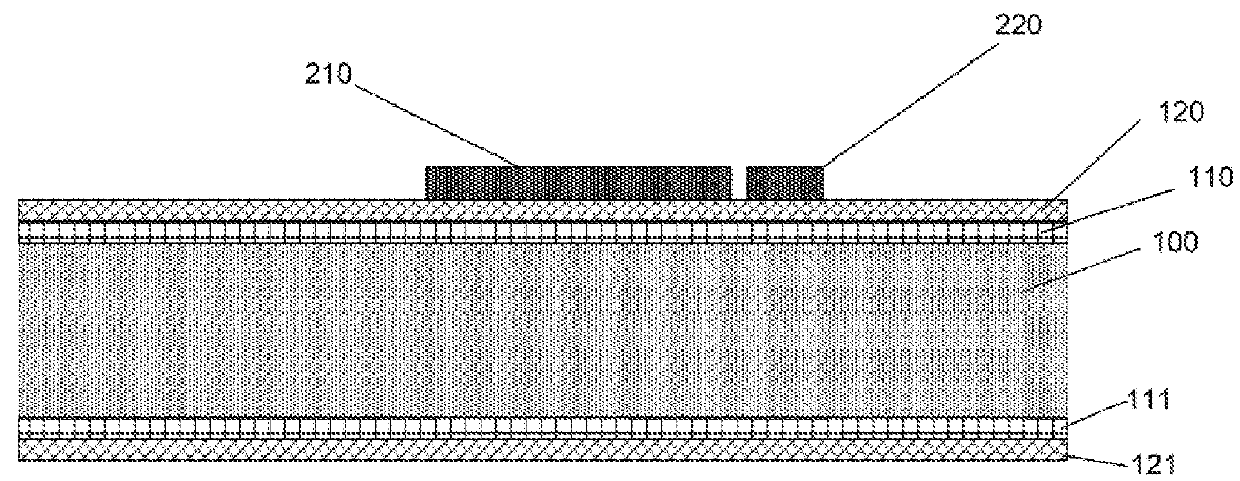
[0028]The preferred micromachining process for making of the said invention starts from the preparation of the isolation cavity process mask and process stop (110 and 111) on the single crystal silicon substrate (100) with a thickness from 0.35 to 0.50 mm. Then the process is formed by the membrane formation for supporting the sensing, elements and the said heat source (120) as shown in FIG. 1. The isolation cavity process mask and process stop (110 and 111) can be made of silicon oxide via thermal oxidization growth in an oven with a thickness of 100 to 300 nm but preferably 150 nm. The membrane material is usually selected to be polyimide or silicon nitride for its mechanical strength. The polyimide membrane is made via spin coating with a thickness of 2 to 8 micro meters. The silicon nitride is preferably made via the low pressure chemical vapor deposition (LPCVD) process with a thickness from 800 to 2000 nm but preferably of 1000 to 1200 nm for the management of the total membra...


PUM


Abstract

The design and manufacture method of a silicon mass flow sensor made with silicon micromachining (a.k.a. MEMS, Micro Electro Mechanical Systems) process for applications of gas flow measurement with highly humidified or liquid vapors is disclosed in the present invention. The said silicon mass flow sensor operates with an embedded heater and an adjacent control temperature sensor beneath the integrated calorimetric and thermal dissipative sensing thermistors. When the condensation takes place at the surface of the said silicon mass flow sensor, the embedded heater shall be turned on to elevate the temperature of the supporting membrane or substrate for the sensing thermistors. The elevated temperature shall be adjusted to above the vaporization temperature with the feedback data of the adjacent temperature sensor such that the surface condensation due to the presence of the liquid vapors in a gas flow can be effectively eliminated.

Description

BACKGROUND OF THE INVENTION[0001]1. Field of the Invention[0002]This invention relates to micromachined silicon sensors or Micro Electro Mechanical Systems (MEMS) mass flow sensing technology that measures the quality of gases. The present invention also relates to thermal mass flow sensors of such gases. This invention additionally provides the design and make of a micromachined mass flow sensor. The present invention specifically relates design and process of making the same for a mass flow sensor for preventing of liquid vapor or liquid condensation of such sensors that will be used to measure the flow at a highly humidified gas medium.[0003]2. Description of the Related Art[0004]Micromachined mass flow sensors (aka silicon flow sensors) are generally made on silicon wafers, and have been widely applied in the past decades in medical, automotive, and many other industries where clean and dry gas flow measurements are demanded for high accuracy, low cost and enhanced performances ...

Claims


Application Information

Patent Timeline
Patent Type & Authority Patents(United States)
IPC IPC(8): G01F1/699G01F1/684G01F1/692
CPCG01F1/699G01F1/6845G01F1/692
Inventor HUANG, LIJICHEN, CHIH-CHANG
Owner WISENSTECH
Why Eureka
Try Eureka