Transmission diffraction element

a technology of diffraction element and grating, which is applied in the field of diffraction element, can solve the problems of small tolerable manufacturing margin at the time of manufacture, difficult to obtain high yield and high diffraction efficiency, and difficult to form the grating convex part having the barrel-shaped cross section, etc., and achieves low cost, high diffraction efficiency, and easy manufacturing.

Active Publication Date: 2016-06-07
ASAHI GLASS CO LTD
View PDF17 Cites 1 Cited by
  • Summary
  • Abstract
  • Description
  • Claims
  • Application Information

AI Technical Summary

Benefits of technology

[0014]The present invention is conceived in view of the above problem, and one object of the present invention is to provide a transmission diffraction element that may be easily manufactured at a low cost, and may have a high diffraction efficiency and a low polarization dependence throughout the entire wavelength region of incident light.

Problems solved by technology

However, in order to obtain the high diffraction efficiency, the cross sectional shape may need to be a barrel shape or the like, and it may be difficult to form the grating convex part having the barrel-shaped cross section.
However, the grating convex part having the trapezoidal cross section may have a narrow wavelength range in which a desired diffraction efficiency is obtainable, and a tolerable manufacturing margin at the time of the manufacture may be small.
Hence, it may be difficult to obtain a high yield and a high diffraction efficiency throughout the entire wavelength region that is to be used.
In addition, a large deposition apparatus may be required to manufacture the 3-layer structure, and the manufacturing process may become complex.
For example, in the case of an optical system in which light emitted from an end of an optical fiber is incident to the diffraction element, when the reflected 1st-order diffracted light is reflected at the end of the optical fiber and again becomes incident to the diffraction element to act as a resonator, the signal intensity may become unstable.

Method used


Image

  • Transmission diffraction element
  • Transmission diffraction element
  • Transmission diffraction element

Examples


example 1

Practical Example 1

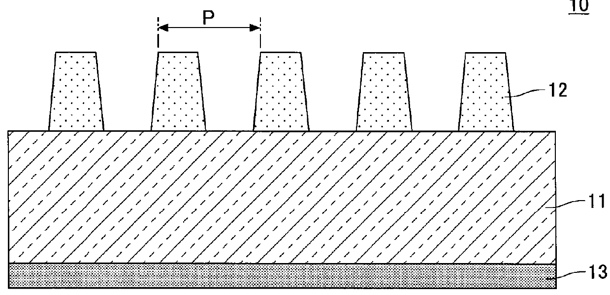
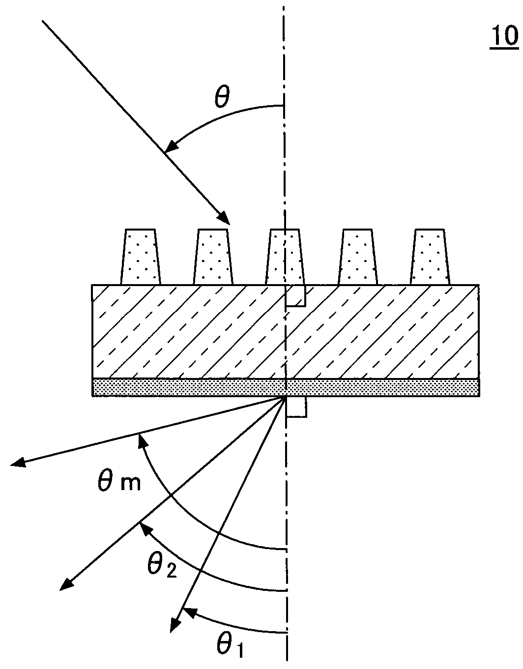
[0063]First, a description will be given of the transmitting diffraction element of a practical example 1 according to the first embodiment. The transmitting diffraction element 10 of this practical example 1 has the cross sectional structure illustrated in FIG. 1, and the diffraction gratings are formed by forming the convex parts 12 with a period of 1040 nm on the transparent substrate 11 having the AR coating 13 formed thereon. In the transmitting diffraction element 10 of this practical example 1, light having a wavelength of 1525 nm to 1575 nm is incident at an angle of 48° with respect to a normal to the surface formed with the convex parts 12.

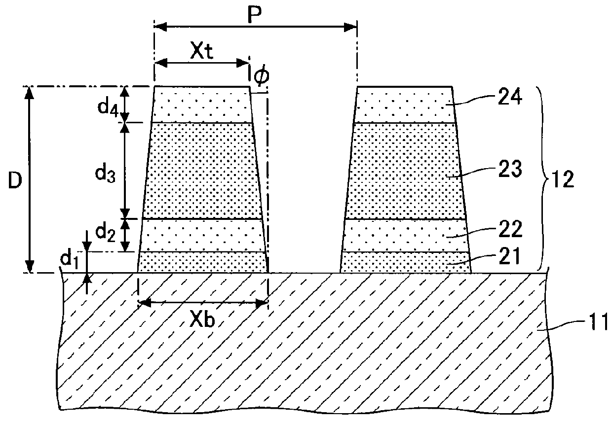
[0064]The convex parts 12 in this practical example 1 has the 4-layer structure formed by the first layer 21, the second layer 22, the third layer 23, and the fourth layer 24. More particularly, the convex part 12 in this practical example 1 has the first layer 21 made of a high refractive index material, Ta2O5, having...

example 2

Practical Example 2

[0077]Next, a description will be given of the transmitting diffraction element of a practical example 2 according to the first embodiment. The transmitting diffraction element 10 of this practical example 2 has the cross sectional structure illustrated in FIG. 1, and the diffraction gratings are formed by forming the convex parts 12 with a period of 1070 nm on the transparent substrate 11 having the AR coating 13 formed thereon. In the transmitting diffraction element 10 of this practical example 2, light having a wavelength of 1570 nm to 1610 nm is incident at an angle of 48° with respect to a normal to the surface formed with the convex parts 12.

[0078]The convex parts 12 in this practical example 2 has the 4-layer structure formed by the first layer 21, the second layer 22, the third layer 23, and the fourth layer 24. More particularly, the convex part 12 in this practical example 2 has the first layer 21 made of a high refractive index material, Ta2O5, having ...

example 3

Practical Example 3

[0089]Next, a description will be given of the transmitting diffraction element of a practical example 3 according to the second embodiment. The transmitting diffraction element 50 of this practical example 3 has the cross sectional structure illustrated in FIG. 4, and the AR coating 53 is formed on one surface of the transparent substrate 51, and the warp adjusting layer 54 is formed on the other surface of the transparent substrate 51 opposite to the one surface. In addition, the diffraction gratings are formed by forming the convex parts 52 with a period of 1040 nm on the warp adjusting layer 54. In the transmitting diffraction element 50 of this practical example 3, light having a wavelength of 1525 nm to 1575 nm is incident at an angle of 48° with respect to a normal to the surface formed with the convex parts 52.

[0090]The convex parts 52 in this practical example 3 has the 4-layer structure formed by the first layer 61, the second layer 62, the third layer 6...


PUM


Abstract

A transmitting diffraction element may include a transparent substrate, and a plurality of convex parts periodically formed on one surface of the transparent substrate, and be configured to diffract incident light to the transparent substrate. Each of the convex parts may include first, second, third, and fourth layers that are stacked on the transparent substrate. The first and third layers may be made of a material having a high refractive index, and the second and fourth layers may be made of a material having a low refractive index that is lower than the high refractive index.

Description

CROSS-REFERENCE TO RELATED APPLICATIONS[0001]This application is based upon and claims the benefit of priority of the Japanese Patent Applications No. 2012-070442 filed on Mar. 26, 2012, and No. 2013-048926 filed on Mar. 12, 2013, the entire contents of which are incorporated herein by reference.BACKGROUND OF THE INVENTION[0002]1. Field of the Invention[0003]The present invention relates to a transmission diffraction element that transmits and diffracts incident light.[0004]2. Description of the Related Art[0005]A device or module, such as a tunable laser, a wavelength selective switch, and an optical spectrum analyzer, may separate (or isolate) light including a plurality of wavelengths, and acquire information such as intensity, phase and the like of the light included for each wavelength. One method of separating the light may use a prism or a diffraction element. The diffraction element in particular may make a grating period short in order to make a diffraction angle difference...

Claims


Application Information

Patent Timeline
Patent Type & Authority Patents(United States)
IPC IPC(8): G02B5/18G02B5/30
CPCG02B5/1866G02B5/3025
Inventor WAKABAYASHI, TAKERUMURAKAWA, MASAHIRO
Owner ASAHI GLASS CO LTD
Why Eureka
Try Eureka