Multi-parameter scattering sensor and methods

Active Publication Date: 2016-06-28
NASA
View PDF12 Cites 17 Cited by
  • Summary
  • Abstract
  • Description
  • Claims
  • Application Information

AI Technical Summary

Benefits of technology

The invention aims to improve the accuracy of measuring the total mass and surface area of particles in an ensemble. This is achieved by adjusting the placement and detection angles of multiple sensors to reduce uncertainty. Additionally, the invention proposes a detection angle that minimizes measurement errors for a moment of the ensemble of particles. This results in more accurate measurements of aerosols.

Problems solved by technology

In any of these situations, the occurrence of fires can jeopardize lives and crew safety, equipment and infrastructure, flight systems, mission objectives, etc.
If suitable provisions are not afforded for fire prevention and mitigation, the hazards can be considerable.
However, designing suitable particulate sensors is challenging.
Conventional state of the art fire detectors suffer from significant detection errors, and the simple strategy of increasing detection sensitivity to decrease response time leads to the problematic likelihood of false alarms.
Existing standards for alarms levels are mass-based, and remain somewhat primitive in their approach and performance.
Furthermore, conventional fire detection systems are, at best, poorly suited to detect reduced-gravity fire signatures such as signatures that may occur on a spacecraft.
Conventional particulate sensors for fire detection thus suffer from poor accuracy and the inability to measure specific properties or multiple properties simultaneously, and typically have a physical package that is unsuitably large, massive, power consumptive, or not mechanically robust for field deployment.
In addition, accurate particulate sensors for detecting particles produced by industrial processes or environmental processes are not currently available.

Method used


Image

  • Multi-parameter scattering sensor and methods
  • Multi-parameter scattering sensor and methods
  • Multi-parameter scattering sensor and methods

Examples


first embodiment

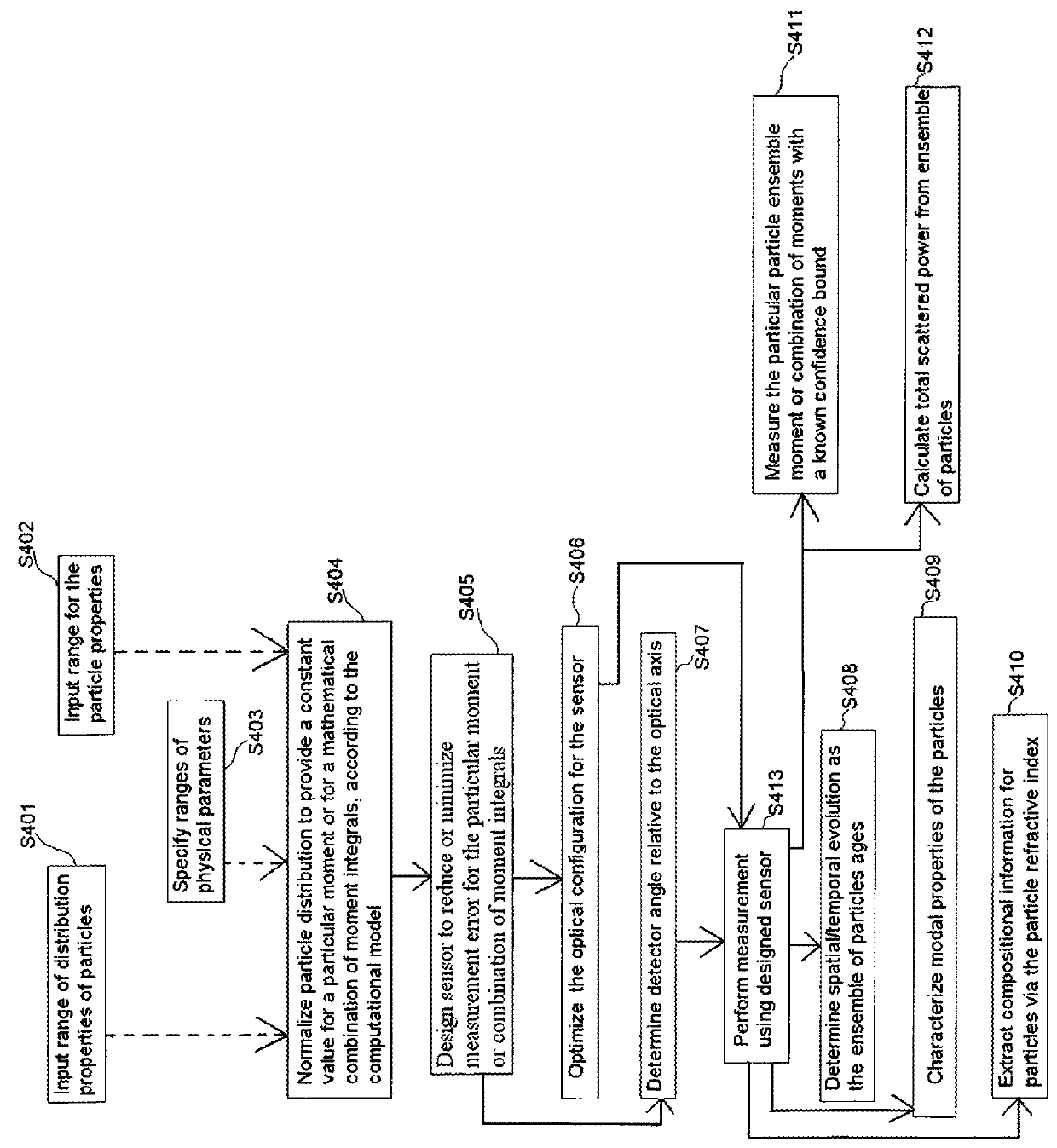
[0158]FIG. 2A is a flow diagram illustrating the design and operation of a sensor for providing accurate particle measurement for a distribution of particles for fire detection, environmental monitoring and other applications, according to the present invention. As shown in FIG. 2A, a range of distribution properties of particles is first input (S401). Exemplary distribution properties are median size, width of distribution, etc. A range for the particle properties may additionally, or alternatively, be input (S402). Exemplary particle properties may be the refractive index, shape, etc. Ranges of physical parameters may additionally, or alternatively, be specified (S403). Exemplary physical parameters include illumination wavelength for radiation incident on the particles, collection aperture for the sensor, collection angle for the sensor, polarization state of radiation.

[0159]The particle distribution is then normalized to provide a constant value for a particular moment or for a ...

second embodiment

[0162]FIG. 2B is a flow diagram illustrating the design and operation of a sensor for determining an aerosol moment with minimum measurement uncertainty, according to the present invention. As shown in the method of FIG. 2B, a parameter range for an aerosol distribution is input (S431). An aerosol moment to be measured is selected (S432), and the computational model is used to determine the angle with respect to an input beam for a detector to minimize the error of measurement of the selected moment (S433). After the angle has been determined, the detector is arranged at the determined angle with respect to an input beam (S434) and the input beam is sent into the aerosol distribution (S435) and the aerosol moment and the uncertainty in measurement of the aerosol moment are output (S436).

third embodiment

[0163]FIG. 2C is a flow diagram illustrating the design and operation of a sensor for optimizing an aerosol moment measurement or determining measurement uncertainty bounds, according to the present invention. One or more ranges for particle properties for an aerosol is / are specified (S450), and either a range for a desired uncertainty of measurement of an aerosol moment by the detector is specified or a range for a detection angle for detecting the aerosol with the detector is specified (S452). Using the computational model, at least one of the following is then determined: a range for uncertainty of measurement of the aerosol moment by the detector, a range for an optimized detection angle for detecting the aerosol with the detector within a range of minimum uncertainty, and a range for an optical design parameter of the detector to optimize the moment measurement (S454).

[0164]The methods shown in the above figures represent just some of the methods for detector design and aerosol...


PUM


Abstract

Methods, detectors and systems detect particles and / or measure particle properties. According to one embodiment, a detector for detecting particles comprises: a sensor for receiving radiation scattered by an ensemble of particles; and a processor for determining a physical parameter for the detector, or an optimal detection angle or a bound for an optimal detection angle, for measuring at least one moment or integrated moment of the ensemble of particles, the physical parameter, or detection angle, or detection angle bound being determined based on one or more of properties (a) and / or (b) and / or (c) and / or (d) or ranges for one or more of properties (a) and / or (b) and / or (c) and / or (d), wherein (a)-(d) are the following: (a) is a wavelength of light incident on the particles, (b) is a count median diameter or other characteristic size parameter of the particle size distribution, (c) is a standard deviation or other characteristic width parameter of the particle size distribution, and (d) is a refractive index of particles.

Description

CROSS REFERENCE TO RELATED APPLICATION[0001]This application claims the benefit from U.S. Provisional Application No. 61 / 355,376, entitled “Multi-Parameter Aerosol Scattering Sensor” filed on Jun. 16, 2010, incorporated by reference herein in its entirety.ORIGIN OF THE INVENTION[0002]The invention described herein was made by an employee of the United States Government and may be manufactured and used by or for the Government for Government purposes without the payment of any royalties thereon or therefore.COMPACT DISKS[0003]The present specification incorporates by reference the entire contents of the attached two compact disks labeled Copy1 and Copy2, whereby Copy1 and Copy2 are duplicate disks. Each of Copy1 and Copy2 disks includes the following files: Fig_4A.txt (Jun. 14, 2011, 8 KB), Fig_4B.txt (Jun. 14, 2011, 8 KB), Fig_5.txt (Jun. 14, 2011, 2 KB), Fig_6A.txt (Jun. 14, 2011, 4 KB), Fig_6B.txt (Jun. 14, 2011, 4 KB), Fig_6C.txt (Jun. 14, 2011, 4 KB), Fig_6D.txt (Jun. 14, 2011, ...

Claims


Application Information

Patent Timeline
IPC IPC(8): G01N15/02G01P5/00G01N21/51
CPCG01P5/001G01N2021/513G01N15/0205G01N15/06G01N15/075
Inventor GREENBERG, PAUL SFISCHER, DAVID G
Owner NASA
Why Eureka
Try Eureka