Surgical instruments for cutting cavities in intramedullary canals

a surgical instrument and intramedullary canal technology, applied in the field of surgical instruments for cutting cavities in intramedullary canals, can solve the problems of unintentional reaching, damage to the cortical wall, and the problem of cutting cancellous bone without damaging the cortical wall or cortical bone structure, so as to achieve the effect of safe creation of cavities

Active Publication Date: 2016-07-05
SMITH & NEPHEW INC
View PDF42 Cites 9 Cited by
  • Summary
  • Abstract
  • Description
  • Claims
  • Application Information

AI Technical Summary

Benefits of technology

[0010]Surgical instruments and procedures are disclosed that enable the injection of an optimal amount of curable resin or putty and / or the placement of an internal fixation device including balloon / expandable devices in an IM canal of a fractured bone. The disclosed instruments enable a surgeon to clear at least a portion of the IM canal of cancellous bone and marrow across the fracture site. As a result, the surgeon can safely create a cavity for injecting or placing curable resin, putty, and / or an internal fixation device without damaging the cortical wall. The disclosed surgical instruments are able to cut cancellous bone in the IM canal without substantially damaging or cutting the cortical wall regardless of profile irregularities of the IM canal. Flexible cutting arms of the disclosed instruments are sufficiently resilient to cut cancellous material while being sufficiently elastic to deform when contacting cortical bone. The disclosed instruments may be used through an entry portal that it is not coaxial with the bone shaft or IM canal. For example, the disclosed instruments can be used with an angled trajectory of up to 45 degrees or up to 90 degrees relative to the bone axis.
[0017]In another general aspect, a method of forming a cavity in a bone, the bone having cortical wall, cancellous bone, an intramedullary canal, and a fracture site, includes drilling an entry port in the bone that is spaced apart from the fracture site, the entry port providing access to the intramedullary canal of the fractured bone, inserting a surgical instrument through the entry port to the intramedullary canal by compressing flexible cutting arms of the surgical instrument, rotating the surgical instrument to remove cancellous bone without substantially damaging the cortical wall, and moving the surgical instrument within the intramedullary canal to create a cavity. The cavity can substantially follow the shape of the cortical wall.

Problems solved by technology

Because such devices are not intended to cut bone, at least a small cavity must be cut or otherwise formed in the cancellous bone in a separate procedure in order to initially insert the balloon-like device.
However, the concept of cutting and removing cancellous bone without damaging the cortical wall or cortical bone structure is problematic.
As a result, drilling cancellous bone with a conventional surgical drill or a rotating cutting tool can cause damage to the cortical wall, especially along narrower portions of an IM canal and cortical wall.
Further, as cancellous bone is much weaker than cortical bone, conventional drilling instruments used in the IM canal have the potential to quickly drill through cancellous bone before unintentionally reaching the cortical wall and surrounding cortical bone.
Further, the above-described balloon compression devices provide no means for removing cancellous bone tissue, which may be necessary for the formation of larger cavities within the IM canal.
However, when using a conventional drilling / reaming device, the surgeon must be concerned with the pre-selected drill / reamer being too large for any part of the IM canal.
If the drill / reamer is not properly selected, the cortical bone along an area where the cortical wall inner diameter is smaller than that of the drill / reamer may be unintentionally cut.
Further, due to variations in the inner diameter of the cortical bone, the surgeon may be forced to select a drill bit or reamer size that is smaller than desired to avoid cutting cortical bone.
Finally, another disadvantage to the prior art drilling / reaming devices is that an entry port for providing access to the IM canal must be axial with the IM canal.
Often, this results in the removal of significant amounts of healthy cortical bone to reach the IM canal, and breaching an articular surface, which leads to joint pain.

Method used


Image

  • Surgical instruments for cutting cavities in intramedullary canals
  • Surgical instruments for cutting cavities in intramedullary canals
  • Surgical instruments for cutting cavities in intramedullary canals

Examples


Embodiment Construction

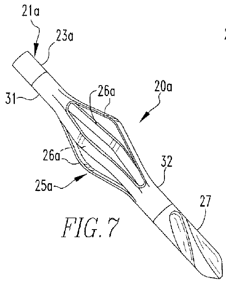
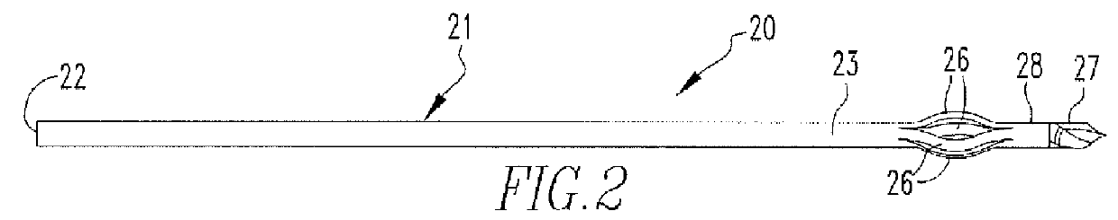
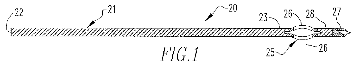
[0035]Turning to FIG. 1, a surgical instrument 20 is shown that includes a flexible shaft 21 with a proximal end 22 and a distal end 23. The proximal end 22 of the shaft 21 may be coupled to a connector for connecting the shaft 21 to surgical drilling instrument, such as the drill 24 of FIG. 17. Alternatively, the proximal end 22 of the shaft 21 may be coupled to a handle or other suitable device for assisting or allowing a surgeon to rotate the instrument 20. Any of these components can also be made as an integral part of the instrument. The distal end 23 the shaft 21 may be coupled directly or indirectly to an expandable cutting device 25 which, as shown in FIGS. 1-3, includes four flexible cutting arms 26. The number of cutting arms 26 may vary but two or more cutting arms 26 are preferred. The cutting arms 26 may be coupled directly or indirectly to a distal nose section 27. For example, a distal shaft or collar section 28 may be disposed between the cutting arms 26 and the dist...


PUM


Abstract

Surgical instruments and procedures are disclosed that enable the injection of an optimal amount of curable resin and / or the placement of an internal fixation device in an intramedullary canal of a fractured bone. The disclosed instruments and procedures enable a surgeon to clear a portion of the canal of cancellous bone and marrow across the fracture site without damaging the cortical wall.

Description

CROSS REFERENCE TO RELATED APPLICATION[0001]This application claims priority to and the full benefit of U.S. Provisional Application Ser. No. 61 / 228,252, filed Jul. 24, 2009, and titled “Surgical Instruments For Cutting Cavities in Intramedullary Canals,” the entire contents of which are incorporated herein by reference.TECHNICAL FIELD[0002]Surgical instruments and procedures are disclosed for selectively forming cavities in intramedullary (IM) canals of bones.BACKGROUND[0003]For purposes of this disclosure, the anatomy of a bone of a human or mammal can be divided into three principal segments: (1) the outer cortical bone that provides a rigid outer structure and weight bearing capabilities of the bone; (2) cancellous bone tissue disposed between the cortical bone and the intramedullary (IM) canal; and (3) the IM canal that passes axially through the cortical bone and cancellous bone tissue. Cancellous bone is substantially weaker than cortical bone. The boundary between the cancel...

Claims


Application Information

Patent Timeline
Patent Type & Authority Patents(United States)
IPC IPC(8): A61B17/16A61B17/32A61B17/3207A61B17/00
CPCA61B17/32002A61B17/164A61B17/1617A61B2217/007A61B17/1631A61B17/320725A61B2017/00526A61B2017/320032A61B2217/005
Inventor RAINS, JAMES K.BLACK, BRIAN L.
Owner SMITH & NEPHEW INC
Why Eureka
Try Eureka