
Transportation refrigeration system with integrated power generation and energy storage

a refrigeration system and transportation technology, applied in the field of thermal energy storage devices and refrigeration systems, can solve the problems of high operating costs, noise restrictions, and operation by using diesel fuel, and achieve the effects of reducing operating costs, reducing operating costs, and improving efficiency

Inactive Publication Date: 2016-07-12
NEW WEST TECH LLC
View PDF37 Cites 40 Cited by
  • Summary
  • Abstract
  • Description
  • Claims
  • Application Information

AI Technical Summary

Benefits of technology

The present invention is a hybrid refrigeration and thermal energy storage system that is designed to eliminate the need for a diesel engine or auxiliary power unit (APU) in refrigered trailers, boxcars, or other air transport spaces. The system can cool large spaces while eliminating the need for a separate TRU diesel engine or APU. It can also reduce the size, cost, weight, and regulatory impacts of conventional battery energy storage and thermal energy storage systems. Additionally, the system can provide cooling when the vehicle is stationary or parked using its thermal energy storage and battery energy storage sub-systems.

Problems solved by technology

First, these systems are characterized by high operating costs due to their large consumption of diesel fuel.
Second, operation by use of diesel fuel raises a number of regulatory issues, including noise restrictions and proven health critical emissions from the diesel engines.
Electrical trailer refrigeration units powered by truck alternators are another one of the systems providing multi-temperature refrigeration, but these systems have been generally limited to smaller trucks and box trucks.
In other applications, such as with a large 53-foot trailer, these systems have proven nonviable because of the constraints of delivering power from the truck to the trailer due to impractical power transfer and operational logistics issues.
The impracticalities in power transfer from the truck include the significant power generation cost and issues in packaging the systems on the truck itself.
There are also significant concerns with transferring high voltage or current from the truck to the trailer.
This split ownership creates operational logistics problems for the delivery of power from the truck to the trailer.
Therefore, implementing truck to trailer power becomes impractical, as the truck must be properly equipped to power the refrigeration system employed by the trailer.
These systems are often used for trucks designed for local delivery and are characterized by much less precise temperature control.
These systems have many short-comings, including their limited heat absorbance capacity, long recharge times for the eutectic plates, the limited temperature control features of the systems and the excessively heavy weights of the plates.
This has generally limited the application of cold plates systems to smaller, local delivery trucks.
While these systems enable diesel-free operation over the road, their initial cost is prohibitively expensive, they are impractically heavy to use for large refrigerated trailer systems, and battery replacement cost further limit their economic feasibility.
Sea containers using electrically-powered VCC place a particularly large current demand on the system's electrical grid aboard ship or from shore power when the unit cycles.
The sea container systems also require significant steady state power requiring oversized power networks or very complex systems to manage the number of units operating and the timing of the cycling.
Recent regulatory activity in the U.S. relating to the diesel engine on TRU units has resulted in additional administrative and economic burdens for fleets operating diesel-powered TRU units.

Method used


Image

  • Transportation refrigeration system with integrated power generation and energy storage
  • Transportation refrigeration system with integrated power generation and energy storage
  • Transportation refrigeration system with integrated power generation and energy storage

Examples


Embodiment Construction

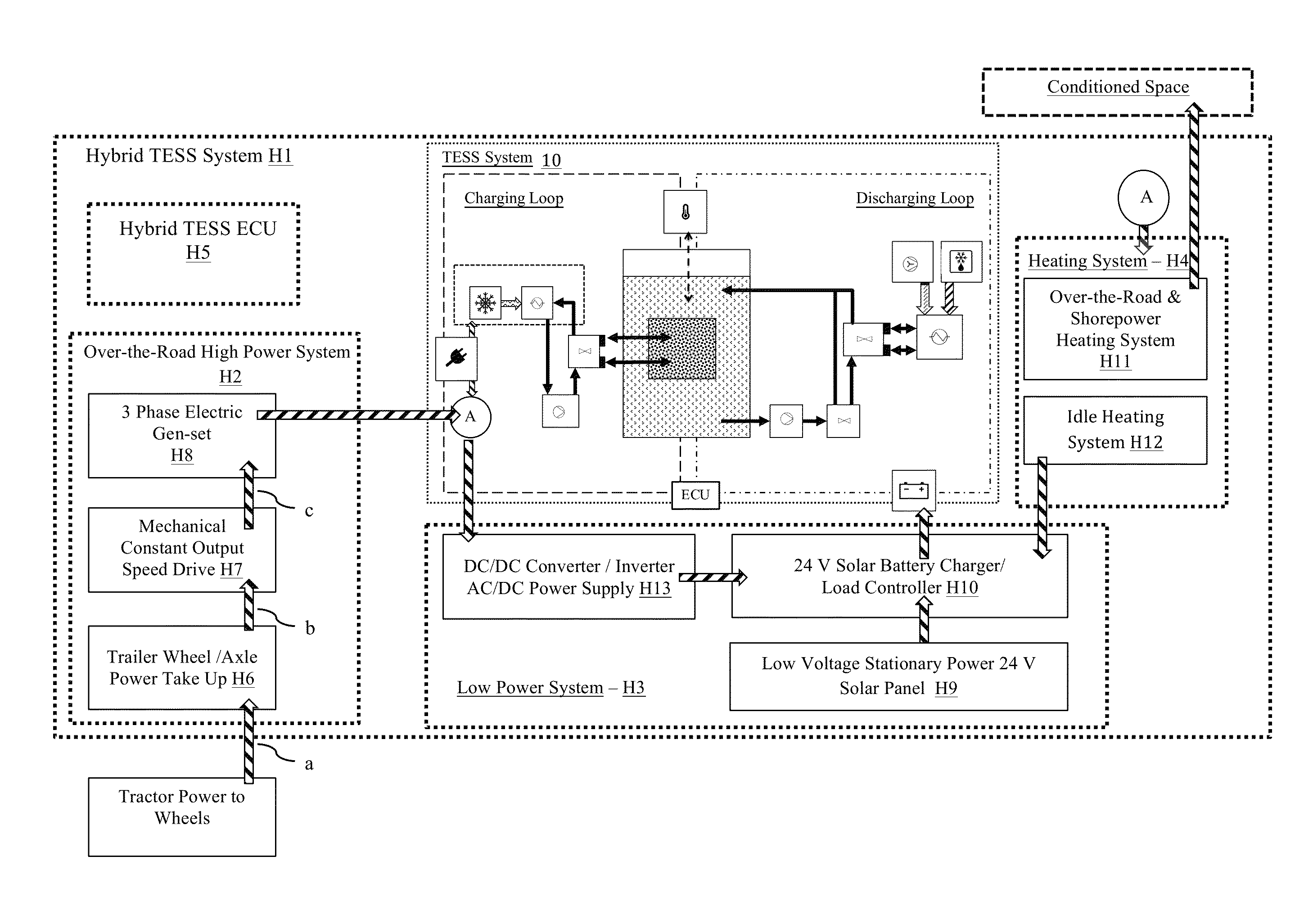
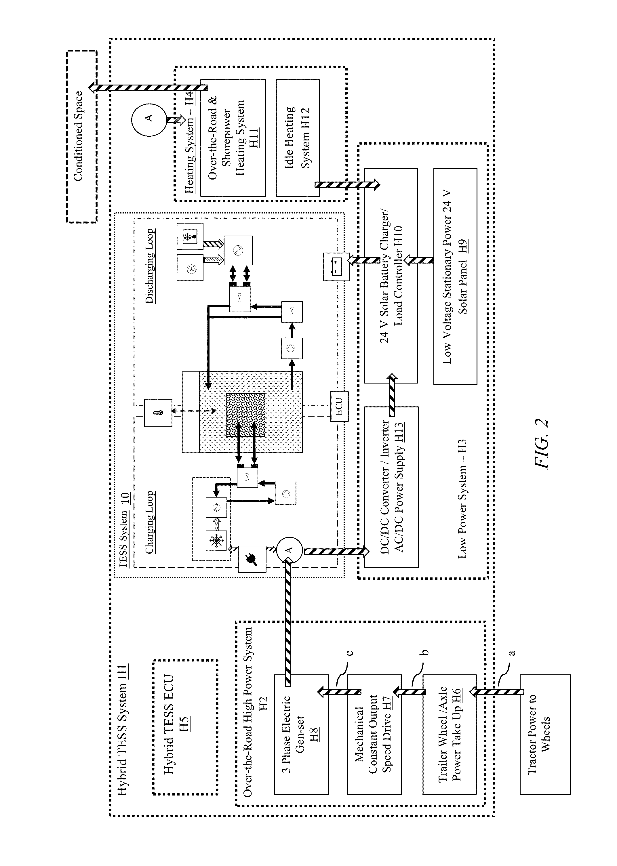
[0080]The present invention provides a hybrid-powered thermal energy storage system (HTESS) that enables the discharge of refrigerated air for cooling cargo or passengers in large compartments, such as the trailer of a semi-truck a transit bus or a rail-container, for typical shift service life periods and indefinitely while in motion over the road or while plugged into shore power. The HTESS system is able to provide refrigeration without the use of a conventional TRU diesel APU engine during the entire service use, or the entire time a 53-foot refrigerated the truck or transit bus is traveling over the road. Additionally, HTESS can provide cooling without operating the VCC system or the truck / bus engine for several hours while the trailer or bus is parked or is idling in traffic.

[0081]The HTES system can charge quickly via shore power or trailer wheel / axle motor power over the road and provide multi-temperature cooling over the road and while stationary, thereby eliminating the di...


PUM


Abstract

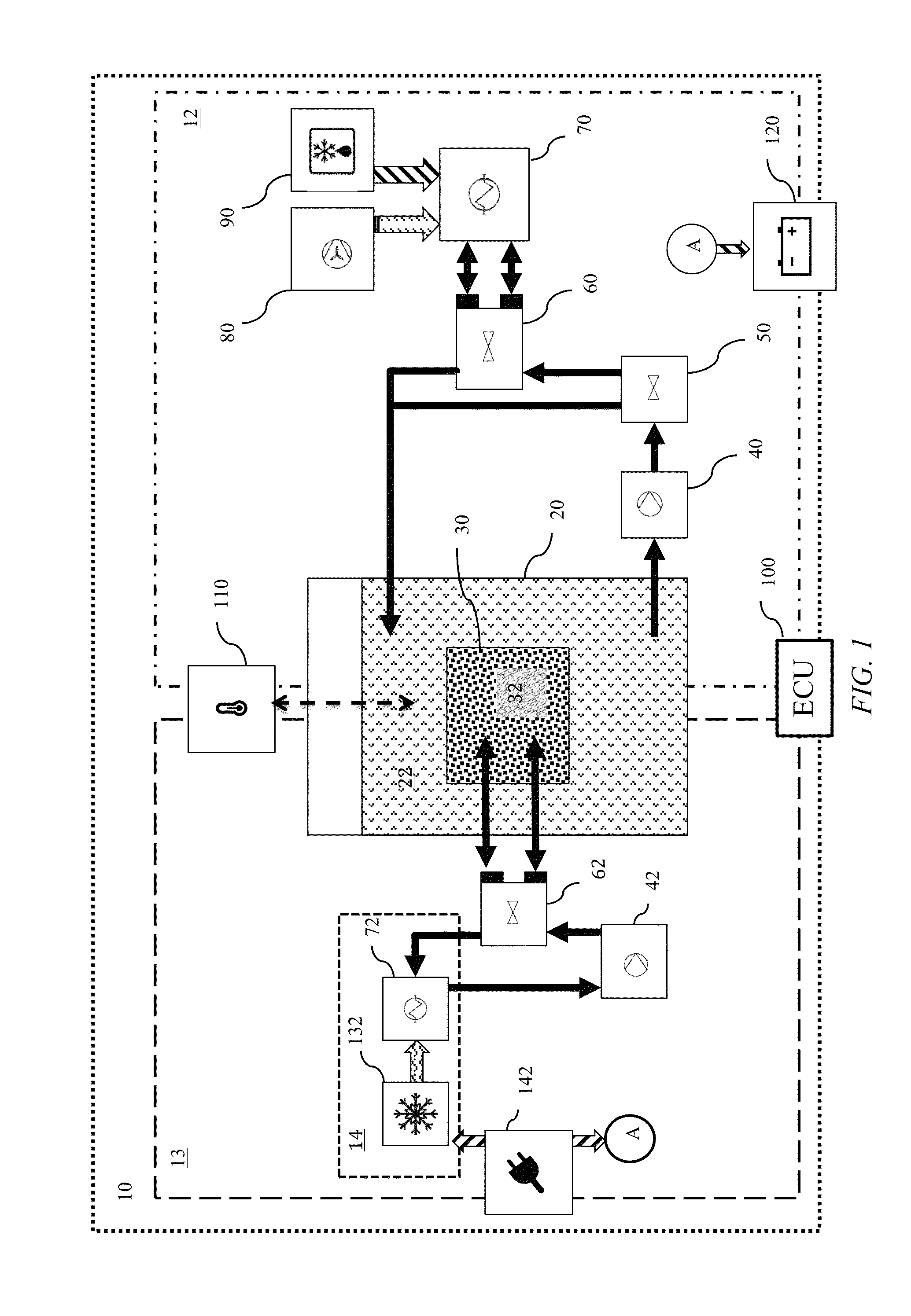
A thermal energy storage system (TESS) that enables the discharge of refrigerated air for cooling cargo or passengers in large compartments, such as the trailer of a semi-truck, for a period of time well in excess of several hours. The TES system is able to provide refrigeration without operating a conventional VCC unit, the truck engine, or the TRU diesel APU engine during all or a significant portion of the period of the typical range of time that a 53 foot refrigerated the truck is traveling over the road. The TES system includes a phase change material (PCM) reservoir, a cooling system-to-WF heat exchanger in fluid communication with the PCM reservoir, and a PCM-to-target heat exchanger in fluid communication with the PCM reservoir. The PCM reservoir contains a phase change material, a working fluid (WF) and a working fluid-to-PCM heat exchanger.

Description

CROSS REFERENCE TO RELATED APPLICATIONS[0001]This application is a continuation-in-part of U.S. application Ser. No. 14 / 151,653, filed on Jan. 9, 2014, which claims the benefit of U.S. Provisional Application 61 / 750,789, entitled, “Flexible Thermal Energy Storage for Transportation Refrigeration”, filed Jan. 9, 2013, the contents of which are herein incorporated by reference.STATEMENT OF GOVERNMENT INTEREST[0002]None.FIELD OF INVENTION[0003]This invention relates to thermal energy storage devices, refrigeration systems and methods. More specifically, this invention relates to thermal energy storage and power systems for transport cooling and refrigeration at a desired temperature range or set-point over extended periods of time.BACKGROUND OF THE INVENTION[0004]A number of systems have been developed over the years to provide multi-temperature refrigeration for the transport of perishable or temperature-sensitive goods in large trailers or containers. The systems are generally design...

Claims


Application Information

Patent Timeline
Patent Type & Authority Patents(United States)
IPC IPC(8): F25B27/02F25B27/00
CPCF25B27/00F25B27/002B60K2001/005B60K2001/008B60P3/20F25D11/003F25D16/00B60K25/08F25B27/005F25B47/025F25D2700/10H02K7/1846
Inventor MCKAY, DANIEL LEE
Owner NEW WEST TECH LLC
Learn More