Eureka AIR delivers breakthrough ideas for toughest innovation challenges, trusted by R&D personnel around the world.

Method of fabricating semiconductor structure

Active Publication Date: 2016-07-12
MARLIN SEMICON LTD
View PDF15 Cites 0 Cited by
  • Summary
  • Abstract
  • Description
  • Claims
  • Application Information

AI Technical Summary

Benefits of technology

The present invention provides a method for improving the coupling ratio of a flash memory device by forming a protruding floating gate. The method includes steps of forming isolation structures on a substrate, adding a first conductive layer, polishing the first conductive layer to make it flat, removing a portion of the isolation structures, adding a second conductive layer, depositing an insulating layer, and adding a third conductive layer. The technical effect of this invention is to enhance the coupling ratio of the flash memory device.

Problems solved by technology

Flash memory cells are often bulky and difficult to fabricate in a desirable space due to complex geometries of the multiple gate layers used to form the control and floating gates.
Accordingly, flash memory cells cannot generally be integrated as compact as other types of memory devices.
However, it is difficult to increase the overlapped area between the control gate and the floating gate in the conventional stacked gate structure.

Method used


Image

  • Method of fabricating semiconductor structure
  • Method of fabricating semiconductor structure
  • Method of fabricating semiconductor structure

Examples


Embodiment Construction

[0020]The present invention will now be described more specifically with reference to the following embodiments. It is to be noted that the following descriptions of preferred embodiments of this invention are presented herein for purpose of illustration and description only. It is not intended to be exhaustive or to be limited to the precise form disclosed.

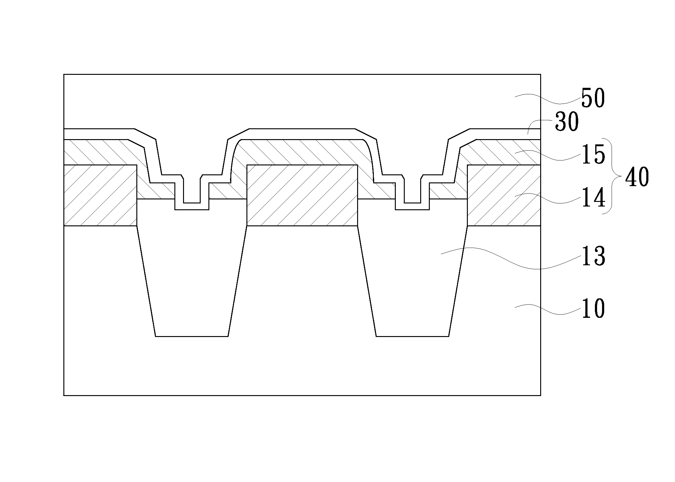
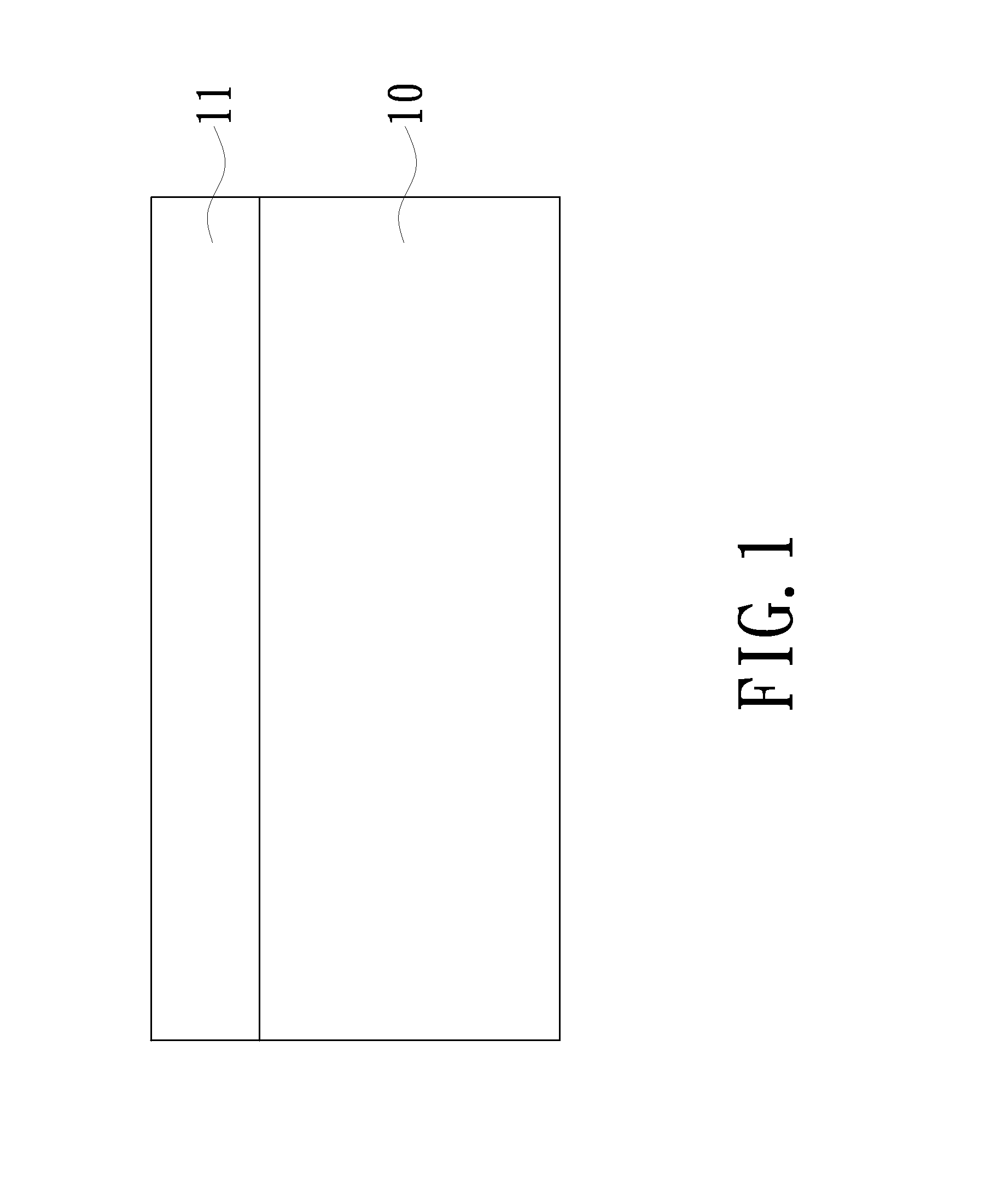
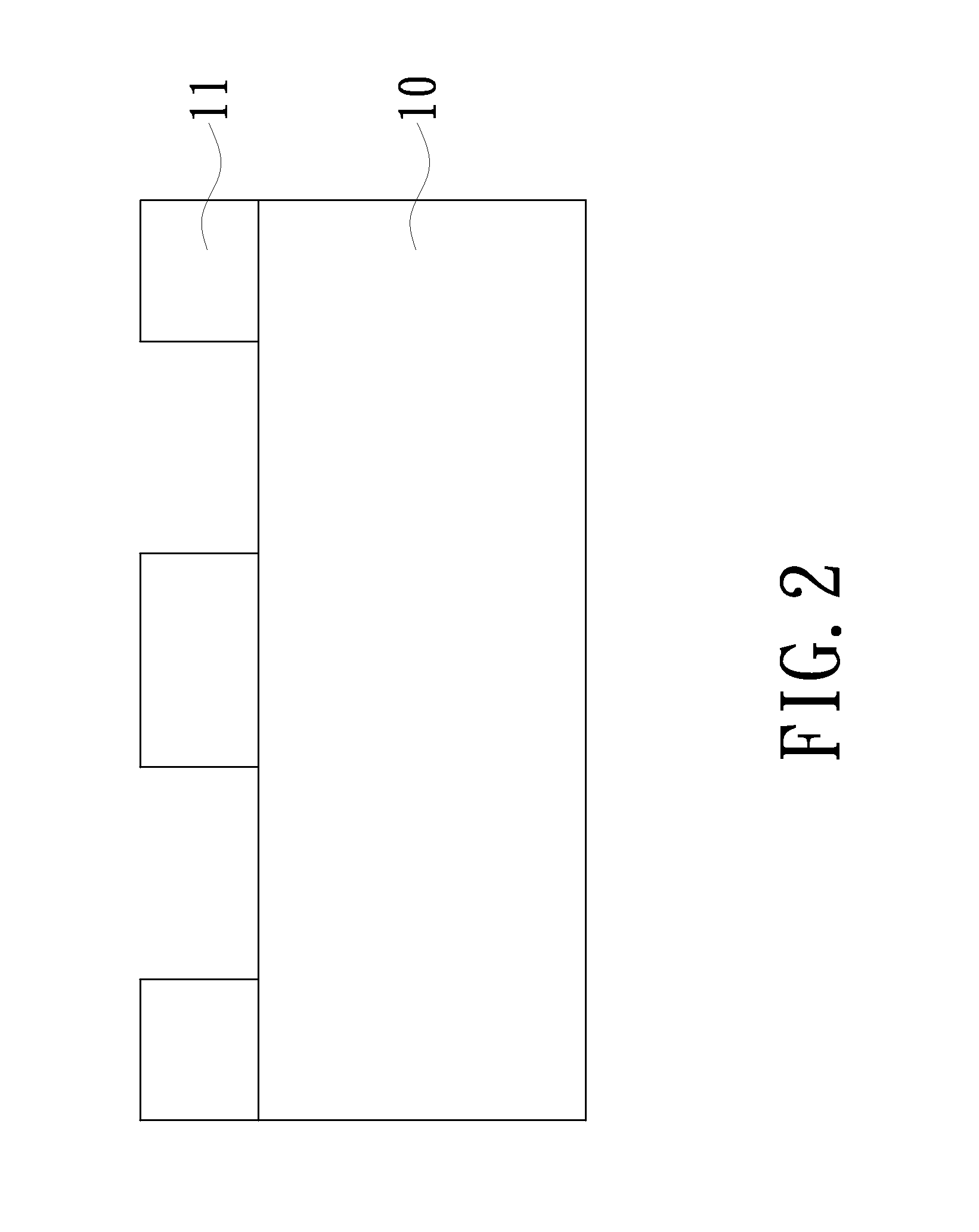
[0021]As show in FIGS. 1-4, a silicon-based substrate 10 is provided. Subsequently, a silicon nitride layer 11 is deposited on the silicon-based substrate 10, and a plurality of shallow trench isolation (STI) grooves 12 is formed by lithography process, in which the etching is generally anisotropic. The anisotropic etching, for example, can be plasma etching or reactive ion etching. Then, the grooves 12 in the substrate 10 are filled with suitable materials such as boro phosphosillicate glass (BPSG), phosphosilicate (PSG), CVD oxide, fluorinated glass (FSG), or the other dielectric materials to form a plurality of isolation struc...


PUM


Abstract

The present invention provides a method for improving gate coupling ratio of a flash memory device and a protruding floating gate is formed. First, a substrate having a plurality of isolation structures is formed. Then, a first conductive layer is formed overlaying the substrate. A chemical-mechanical polishing process is performed to planarize the first conductive layer. After that, a portion of the isolation structures is removed, and a second conductive layer is formed overlaying the first conductive layer and the isolation structures. Finally, a lithography process with a photomask can be used to define a mask that covers the first conductive layer and the second conductive layer, and then an insulating layer is deposited overlaying the substrate, so that a third conductive layer is formed overlaying the insulating layer.

Description

FIELD OF THE INVENTION[0001]The invention relates to a method of fabricating a semiconductor structure, and more particularly to a method of fabricating a protruding floating gate of flash memory.BACKGROUND OF THE INVENTION[0002]Flash memory cells are often bulky and difficult to fabricate in a desirable space due to complex geometries of the multiple gate layers used to form the control and floating gates. Accordingly, flash memory cells cannot generally be integrated as compact as other types of memory devices.[0003]It is the general trend in the semiconductor market to manufacture devices with miniaturized dimensions, lower operation voltage, lower cost, higher speed, etc. The gate coupling ratio (GCR) between the floating gate and the control gate affects the operating voltage and device speed. The read / write method of a flash memory is affected by means of electrons transferring between the floating gate and the source / drain gate. Generally, the larger a gate coupling ratio bet...

Claims


Application Information

Patent Timeline
IPC IPC(8): H01L21/76H01L21/321H01L29/49H01L21/8234H01L29/66H01L21/3205
CPCH01L29/66825H01L21/823481H01L29/4925H01L21/3212H01L21/32055H01L29/40114H10B41/30
Inventor MA, CHU-MINGLIN, CHUN-YIHUANG, HUNG-CHICHUNG, HSIEN-TA
Owner MARLIN SEMICON LTD
Why Eureka
Eureka Blog
Learn More