
Eddy current inspection probe

a technology of eddy current and probe, which is applied in the direction of fluid tightness measurement, instruments, nuclear elements, etc., can solve the problems of increasing the rotational material loss, the centering mechanism of the probe, and the single probe not accessing all the tubes in the steam generator. , to achieve the effect of stopping the rotational limitation of the pivot coupling

Active Publication Date: 2016-07-19
WESTINGHOUSE ELECTRIC CORP
View PDF20 Cites 0 Cited by
  • Summary
  • Abstract
  • Description
  • Claims
  • Application Information

AI Technical Summary

Benefits of technology

[0021]In still another embodiment, each set of rollers includes two rollers that move radially together. Additionally, in one given embodiment, a stop is provided for limiting the degree of rotation of the pivot coupling between the nondestructive sensor section and the tail section. Preferably, the stop limits rotation of the pivot coupling between the nondestructive sensor section and the tail section by preventing axial rotation of the tail section relative to the nondestructive sensor section.

Problems solved by technology

One problem with the prior art eddy current probes is that a single probe does not access all the tubes in a steam generator.
A second problem with current eddy current probes is the probe centering mechanism.
The relatively small surface area of contact between the probes and tube increases radial material loss due to wear.
A further drawback of the probe centering pads is that each pad is compressed, the amount of deflection is independent from one pad to another pad.
Side loads developed as the probe traverses bends in the tubing can adversely impact the centering of the probe.
Additionally, the axial location of probe centering pads relative to the probe inspection coil can cause the coil to contact the tube surface as the probe traverses bends, which can adversely affect proper interpretation of the sensor signals.
Another problem currently experienced is probe electrical signal failures.
An additional difficulty currently encountered during eddy current inspection is in regard to inserting the probe into the tube.
In many cases, the friction due to buckling will continue to increase the buckling load and further increase friction until it is not possible to insert the probe regardless of the force applied.
Since the probe position is measured externally by encoding the flexible cable displacement, buckling of the flexible cable also causes loss of probe position accuracy.
As previously described, there are a number of problem areas with current eddy current inspection techniques.

Method used


Image

  • Eddy current inspection probe
  • Eddy current inspection probe
  • Eddy current inspection probe

Examples


Embodiment Construction

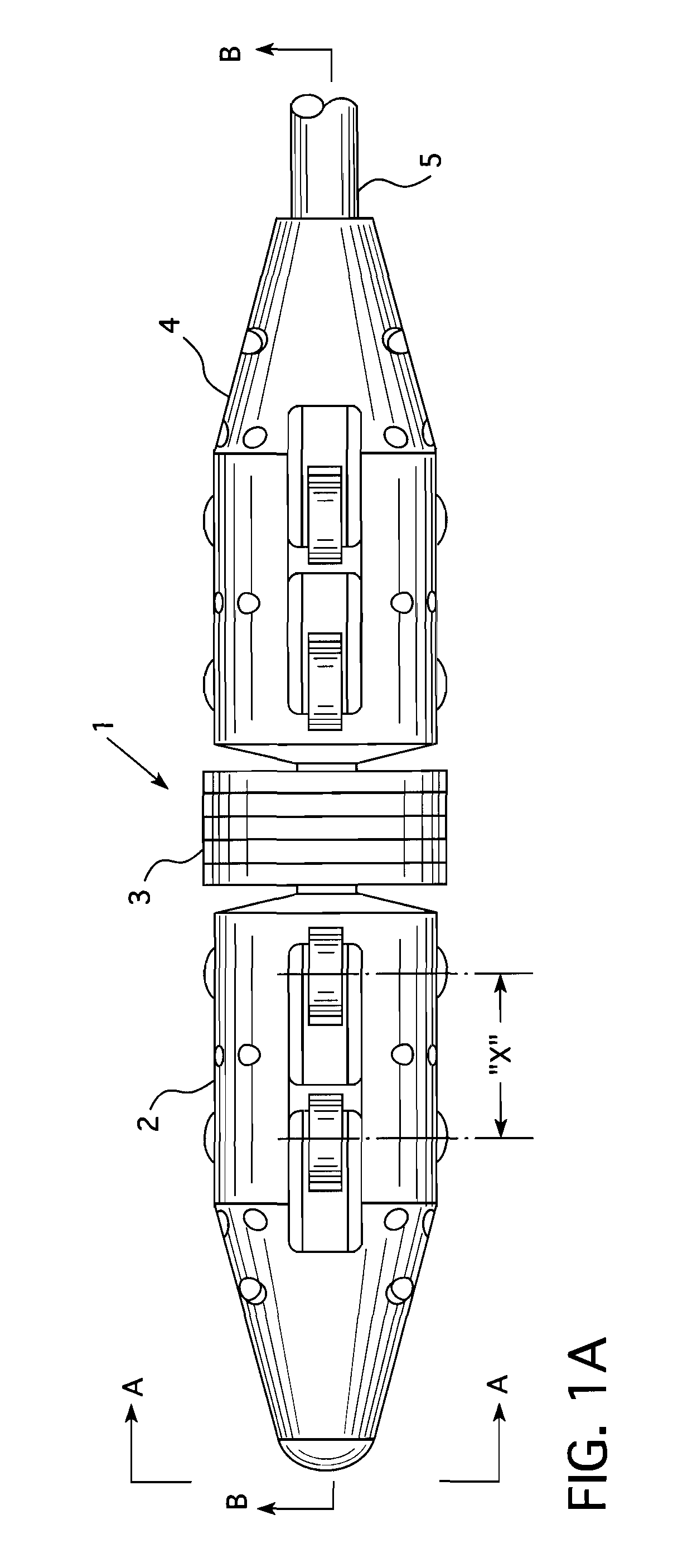
[0031]FIG. 1a shows a plan view of an eddy current probe assembly 1 that incorporates the principles of this invention though it should be appreciated that a probe assembly incorporating these principles can employ any one of a number of nondestructive sensors and should not be limited to just the use of an eddy current probe. The three main parts of the probe assembly 1 are the nose assembly 2, coil assembly 3 and tail assembly 4. Flexible cable 5 is used to translate the probe assembly 1 along the interior of the tube.

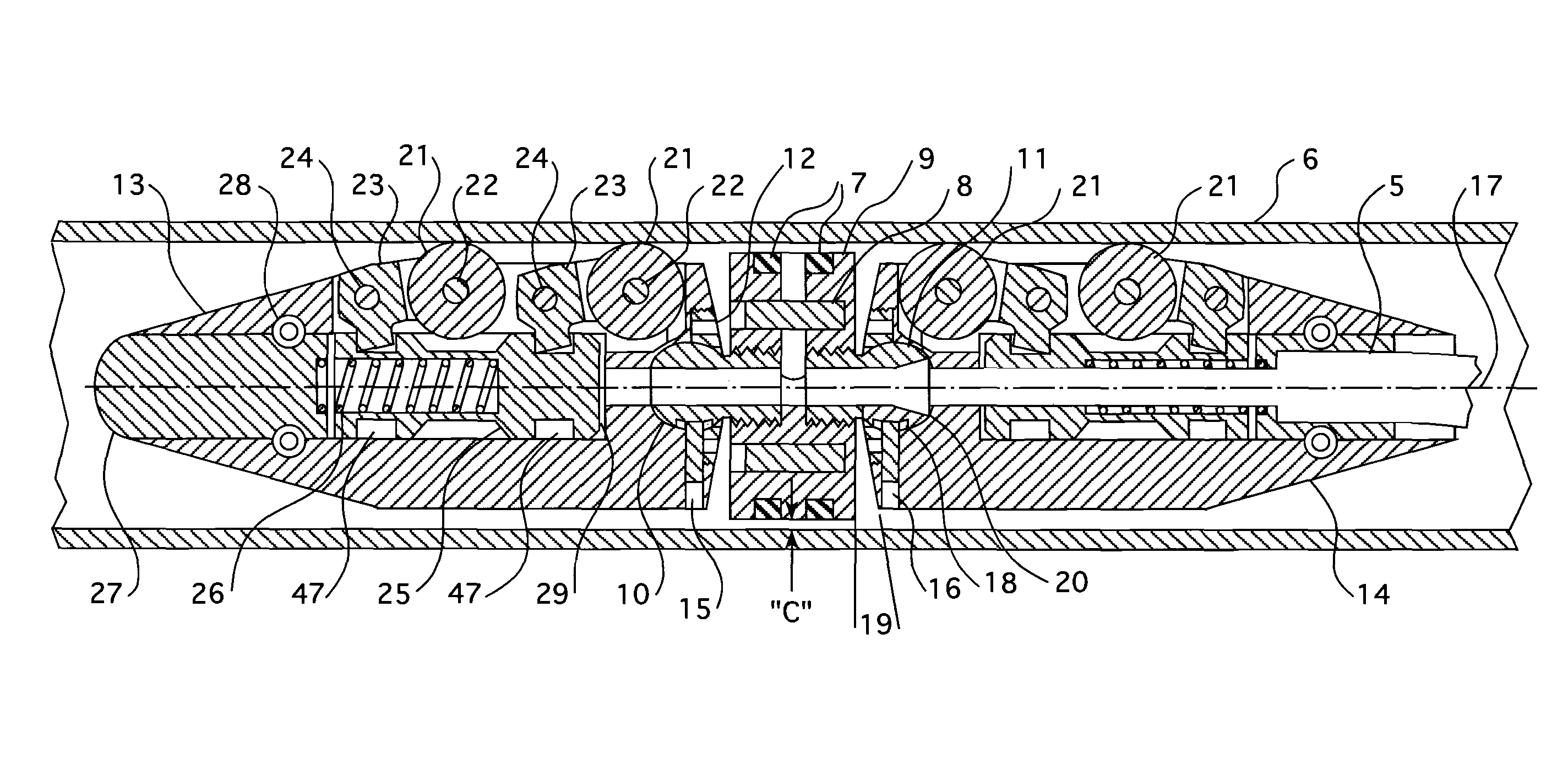
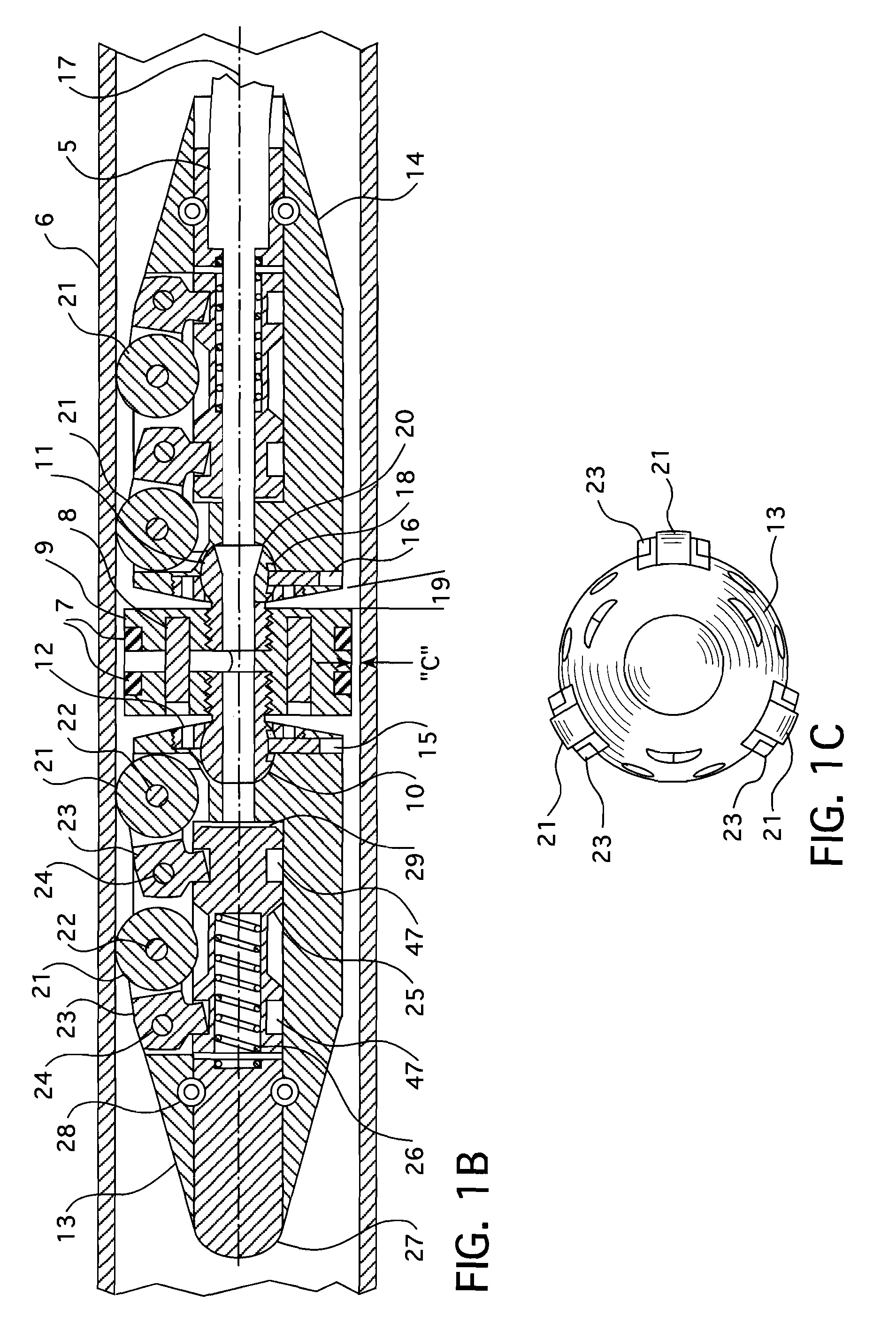
[0032]FIG. 1b shows a cross sectional view of the probe assembly 1 shown in FIG. 1a with section B-B taken through the center of the probe assembly, positioned within a tube 6 to be inspected. While various coil configurations are used in eddy current probes, a typical bobbin probe configuration is shown with circumferential coils 7 along with permanent magnet 8 fixed by means of coil support 9. Unique to this invention is the means to position the coils 7 relative t...


PUM

PropertyMeasurementUnit
lengthaaaaaaaaaa
radiusaaaaaaaaaa
radiusaaaaaaaaaa

Abstract

A probe for transporting a nondestructive inspection sensor through a tube, that employs wheels to reduce friction. The radial travel of the wheels are mechanically linked through a cam and axially reciprocal plunger arrangement that centers the probe at tube diameter transitions. Internal wire bending is minimized and a dynamic seal is provided to facilitate an insertion force at the probe and reduce or eliminate compressive load buckling of the flexible cable carried by the probe. Like the wheel arrangement, radial travel of the seal segments are mechanically linked to provide probe centering.

Description

CROSS REFERENCE TO RELATED APPLICATION[0001]This application claims priority under 35 U.S.C. §119(e) from Provisional Application Ser. No. 61 / 661,441, entitled “Eddy Current Inspection Probe,” filed Jun. 19, 2012.BACKGROUND[0002]1. Field[0003]This invention pertains generally to the nondestructive examination of tubular specimens and, more particularly, to an inspection probe for the nondestructive examination of the structural integrity of heat exchanger tubing.[0004]2. Related Art[0005]In pressurized water reactor nuclear power plants, steam generators convert the thermal energy of water from the reactor coolant to steam to drive turbine electric generators. In order to transfer the heat while maintaining separation between the high pressure water that flows through the reactor core and the lower pressure water that is converted to steam, steam generators are constructed of thousands of small diameter tubes which provide a large surface area for heat transfer. The number of tubes ...

Claims


Application Information

Patent Timeline
Patent Type & Authority Patents(United States)
IPC IPC(8): G01R1/067G01M3/00G01N27/90
CPCG01R1/067G01M3/005G01N27/902G21C17/017G21C17/013F16L55/30F16L2101/30
Inventor HAWKINS, PHILLIP J.PETROSKY, LYMAN J.
Owner WESTINGHOUSE ELECTRIC CORP
Learn More