Sequential circuit with current mode error detection

a current mode and circuit technology, applied in logic circuits, digital circuit testing, electric pulse generators, etc., can solve the problems of stscl to be designed by hand, modern digital design flow cad tools do not support stscl, etc., to achieve larger voltage and temperature tolerance, and reduce the effect of sensitivity to pvt variations

Active Publication Date: 2016-07-19
MINIMA PROCESSOR OY
View PDF17 Cites 0 Cited by
  • Summary
  • Abstract
  • Description
  • Claims
  • Application Information

AI Technical Summary

Benefits of technology

The invention aims to reduce the impact of changes in process parameters such as PVT variations and timing errors, while also allowing for better tolerance of larger voltage and temperature variations. It enables the use of subthreshold CMOS circuits and helps to mitigate the negative effects of these variations.

Problems solved by technology

Modern digital design flow CAD tools do not support STSCL, which forces STSCL to be designed by hand.

Method used


Image

  • Sequential circuit with current mode error detection
  • Sequential circuit with current mode error detection
  • Sequential circuit with current mode error detection

Examples


Embodiment Construction

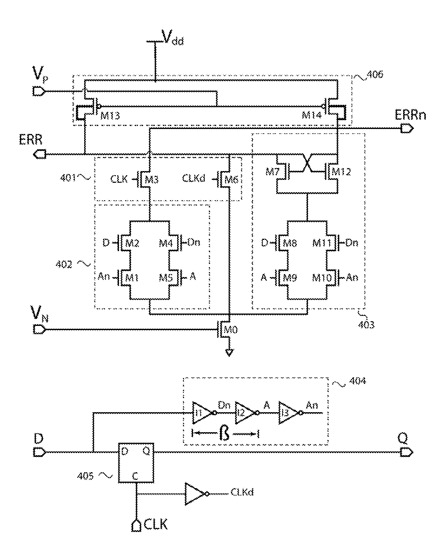
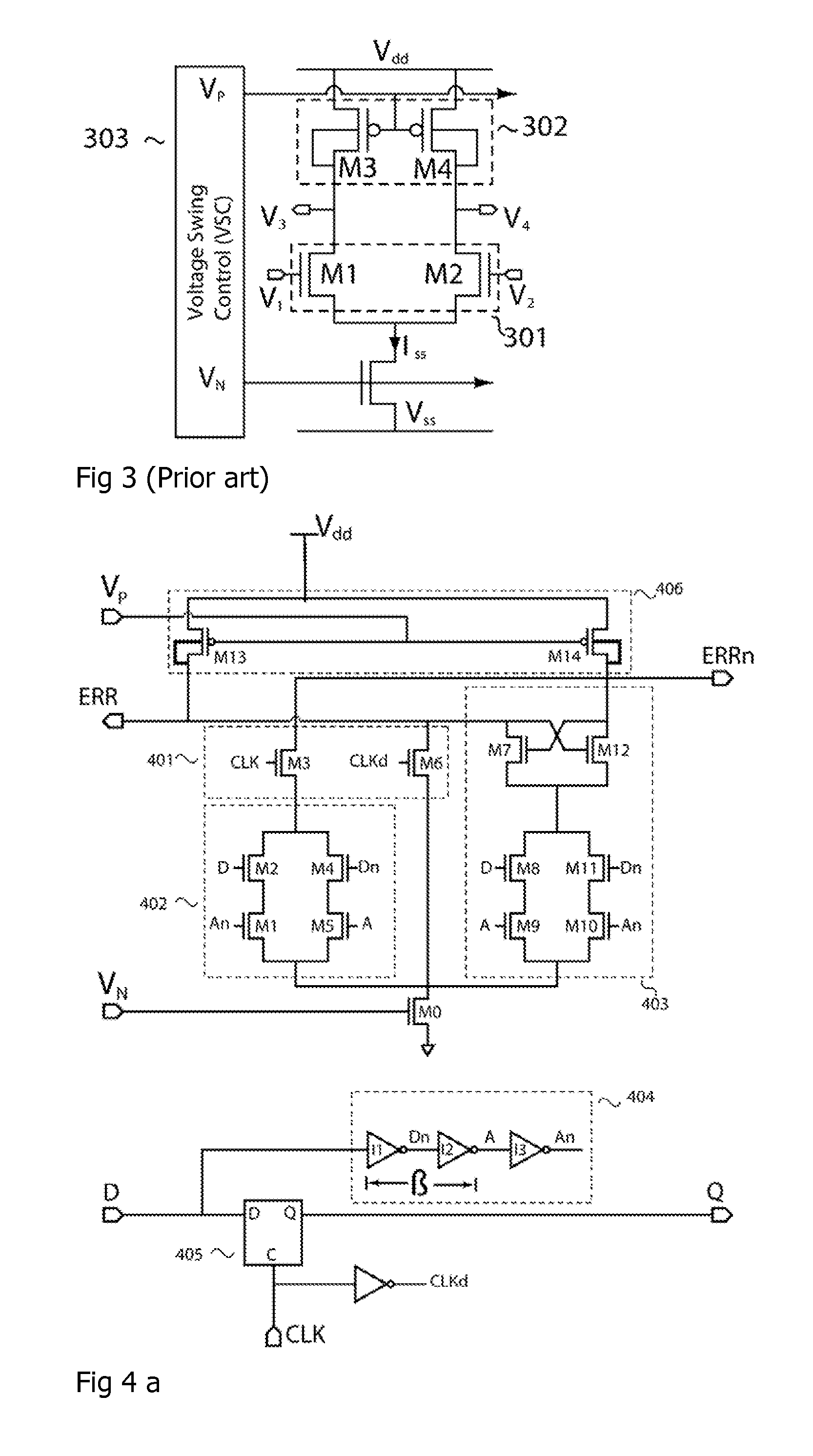
[0019]An embodiment of our invention, a Sequential Circuit with Current Mode Error Detection (SCCMED), is shown in FIG. 4a. This circuit, described in more detail below, may be used, for example, to replace traditional master slave flip flop circuits in the critical paths of pipelined logic. The error detection feature can then be further used to attain gain in performance, power, and / or yield. The use of current-mode avoids the power and performance penalty of using conventional circuits designed for nominal operating voltage ranges. As only the error detection is designed with current mode logic, it is simple to integrate the circuit into a static CMOS logic pipeline which has been designed with conventional CAD digital design flow.

[0020]The block diagram of the Current Mode Sequential Circuit with Error Detection is shown in FIG. 4(a). It generally consists of a current mode transition detector (401, 402, 403), a delay line (404), a sequential element such as a latch (405), a loa...


PUM


Abstract

A sequential circuit with transition error detector including a sequential element with an input that is asserted to the output during the second clock phase of a two phase clock signal, a transition error detector coupled to the sequential element input to assert an error signal if a transition occurs at the sequential element input during the second clock phase but not to assert during the first clock phase, wherein a transition error detection circuit comprises a current mode circuit as a detection circuit for transition timing error detection from signals derived from the sequential element clock signal and input signals.

Description

BACKGROUND[0001]1. Field of the Disclosure[0002]The invention relates to combinatory logic timing error detection and especially to improvements to subthreshold CMOS devices by a use of a type of new timing error detection circuit.[0003]2. Description of Related Art[0004]In conventional digital design flow, combinational logic delay constraints are static in the sense that the resulting circuit from synthesis must meet the worst case operation condition delays in order to guarantee the circuit operation. If the run-time delay is longer than analyzed during the design time, correct circuit operation cannot be secured. In a conventional design, meeting timing requirements introduces overdesign leading to both area and power—dynamic and static—consumption increase in the system. On the other hand, a timing error detection (TED) system equipped with Error-Detection Sequential (EDS) latches (Bowman, K. A.; et. al. “Energy-Efficient and Metastability-Immune Resilient Circuits for Dynamic ...

Claims


Application Information

Patent Timeline
Patent Type & Authority Patents(United States)
IPC IPC(8): H03K19/003H03K3/012G01R31/317G01R31/28H03K3/037
CPCH03K19/003G01R31/31725H03K3/012H03K3/0375
Inventor TURNQUIST, MATTHEWKOSKINEN, LAURIMAKIPAA, JANILAULAINEN, ERKKA
Owner MINIMA PROCESSOR OY
Why Eureka
Try Eureka