Electrical current sensor with grounded magnetic core

a technology of electric current and magnetic core, which is applied in the direction of electrical measurements, instruments, measurement devices, etc., can solve the problems of increasing the cost of manufacturing and assembling the magnetic core, affecting the measurement signal, so as to achieve reliable and robustness, economic production and assembly

Active Publication Date: 2016-07-26
LEM INT SA
View PDF23 Cites 1 Cited by
  • Summary
  • Abstract
  • Description
  • Claims
  • Application Information

AI Technical Summary

Benefits of technology

[0006]An object of this invention is to provide an electrical current transducer for electrical current sensing that is economical to produce and assemble, and that is reliable and robust.

Problems solved by technology

A fluctuating voltage or current in the primary conductor may adversely influence the measurement signal because of the capacitive coupling between the primary conductor and the magnetic core.
A difference in potential between the magnetic core and the measurement signal processing circuit may also adversely influence the measurement signal and it is therefore common to connect the magnetic circuit electrically to a reference voltage, namely ground, of the signal processing circuit.
The electrical connection to the magnetic core increases the cost of manufacturing and assembling the magnetic core, and may also affect the magnetic properties (magnetic permeability) of the material of the core.
Also, the electrical connection to the magnetic core, depending on the type of core and application, may be susceptible to rupture, for example through wear and vibrations, leading to a faulty electric current measurement signal that goes unnoticed, or requires replacement of the sensor.
In view of the large surface area of the circuit board and the relatively high mass of the magnetic core, this configuration is however costly and not sufficiently robust for certain applications, in particular when subjected to vibration, mechanical shocks and large thermal operating ranges

Method used


Image

  • Electrical current sensor with grounded magnetic core
  • Electrical current sensor with grounded magnetic core
  • Electrical current sensor with grounded magnetic core

Examples


Embodiment Construction

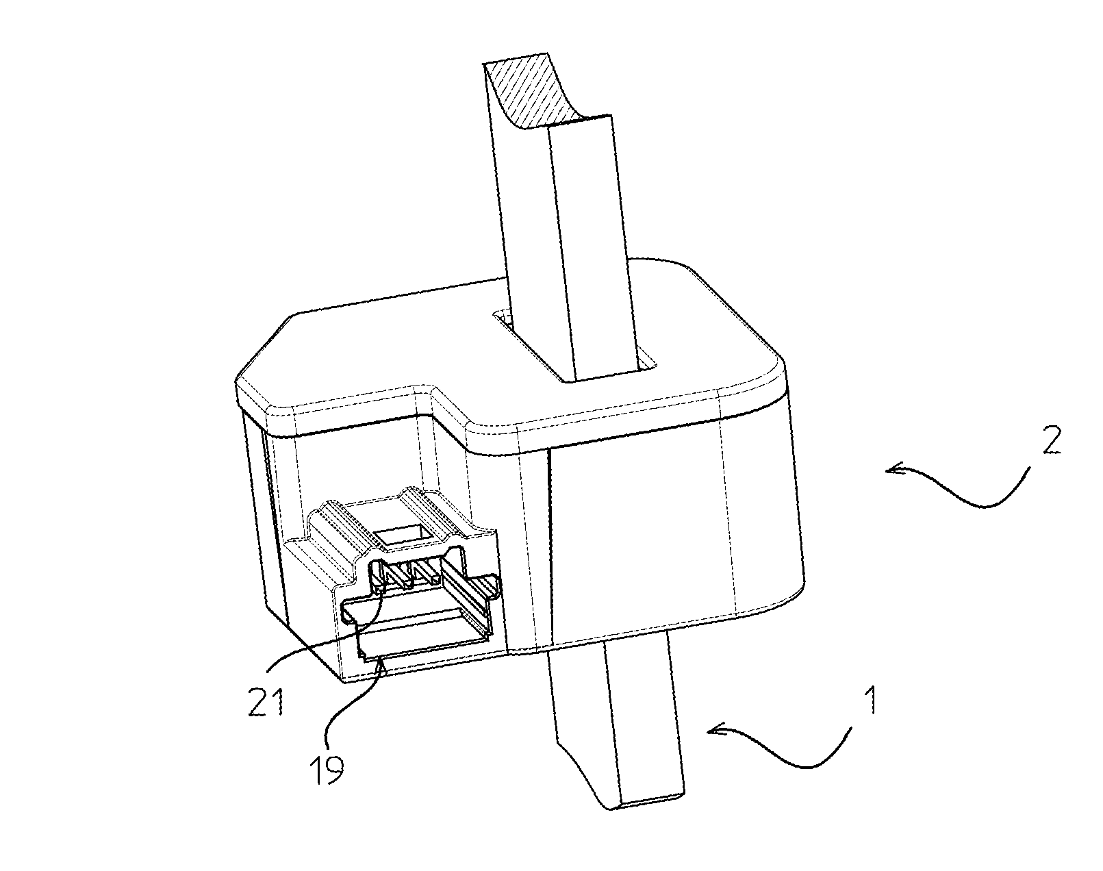
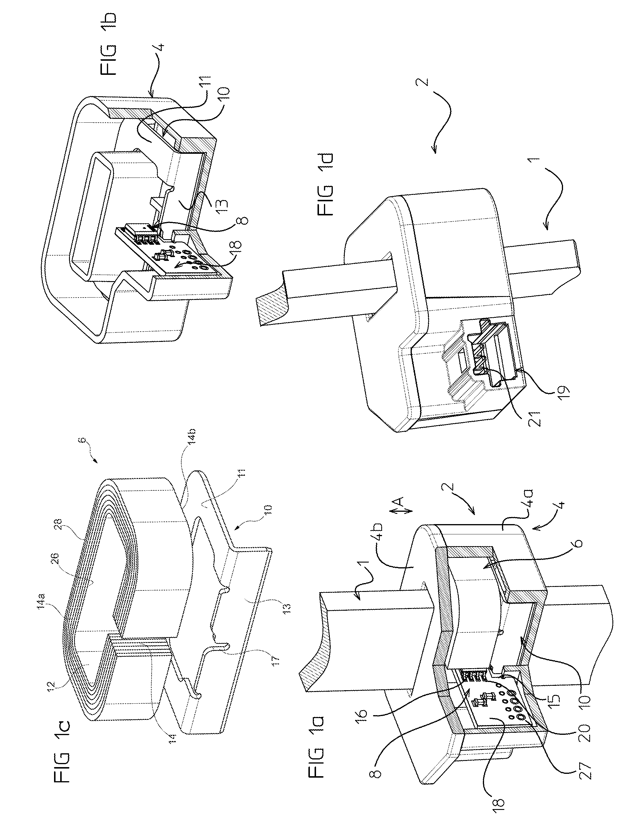
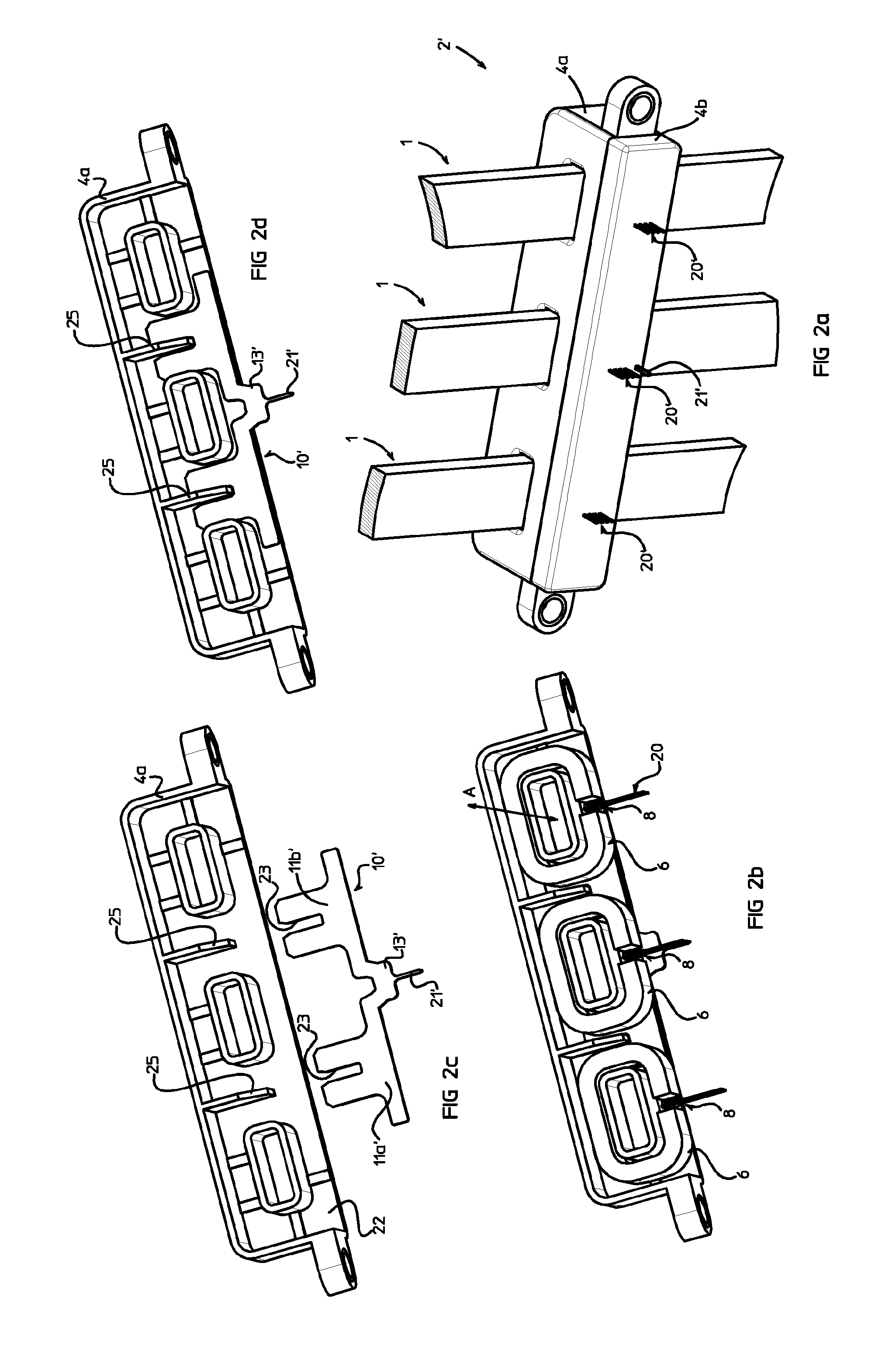
[0031]Referring to the figures, in particular FIGS. 1a-1d, an electrical current sensor 2 comprises a housing 4, a magnetic core 6, a magnetic field detector 8, and a grounding element 10, 10′, 10″, 10′″.

[0032]In a preferred embodiment, the magnetic core 6 is made of a wound strip of thin high magnetic permeability sheet material so as to form stacked concentric ring layers, from a radially innermost ring layer 26 to a radially outmost ring layer 28. The thin edges of the strip layer define opposed lateral sides 14a, 14b of the magnetic core. Magnetic materials with high magnetic permeability are known and for instance include FeSi or FeNi alloys.

[0033]The magnetic core may also be formed from a stack of sheets of a material with high magnetic permeability, or of single piece ferrite, as is well-known in the art.

[0034]The magnetic core surrounds an opening or passage 12 intended to be traversed by a primary conductor 1 through which the current to be measured flows. The magnetic cor...


PUM


Abstract

An electrical current transducer comprising a housing, at least one magnetic core comprising an air gap and defining a central passage configured to receive a primary conductor carrying a primary current to be measured through the central passage, a magnetic field detector positioned at least partially in the air gap, and a grounding element. A lateral surface of the magnetic core is positioned against the grounding element without direct fixed attachment between the magnetic core and the grounding element, and the grounding element overlaps the magnetic core to an extent configured to ensure that a capacitive coupling (C3) between the magnetic core and the grounding element is greater than a capacitive coupling (C2) between the magnetic core and the magnetic field detector.

Description

[0001]The present invention relates to an electrical current sensor with a grounded magnetic core.BACKGROUND OF THE DISCLOSURE[0002]Electrical current transducers for current sensing applications typically comprise a magnetic core made of a high permeability magnetic material, surrounding a central cavity through which passes a primary conductor carrying the current to be measured. The magnetic core may typically have a generally rectangular or circular shape and be provided with an air-gap in which a magnetic field sensor, such as a Hall effect sensor, is positioned. The magnetic flux generated by the electrical current flowing in the primary conductor is concentrated by the magnetic core and passes through the air-gap. The magnetic field in the air-gap is representative of the primary current. In current transducers of the open-loop type, the magnetic field sensor in the air-gap generates an image of the current to be measured that represents the measurement signal. In current sen...

Claims


Application Information

Patent Timeline
Patent Type & Authority Patents(United States)
IPC IPC(8): G01R15/20G01R19/00
CPCG01R19/00G01R15/207
Inventor LEPINE, GERARDVO, VINH THOLABBE, ARNAUD
Owner LEM INT SA
Why Eureka
Try Eureka