X-ray detectable adhesive bandage and method of manufacturing X-ray detectable adhesive bandage
a technology which is applied in the field of x-ray detection and adhesive bandage and the method of manufacturing x-ray detection adhesive bandage, can solve the problems of low yield, relatively complicated manufacturing steps, and too thin aluminum foil to be detected by an x-ray inspection apparatus, so as to improve the yield and reduce the cost. the effect of manufacturing complexity and simplified process
- Summary
- Abstract
- Description
- Claims
- Application Information
AI Technical Summary
Benefits of technology
Problems solved by technology
Method used
Image


Examples
first embodiment
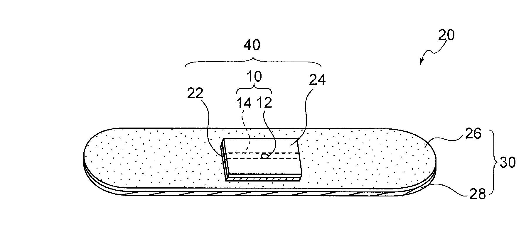
[0047]As shown in FIGS. 1A to 1B, a first embodiment of the invention is an X-ray detectable adhesive bandage 20 including: a pressure-sensitive adhesive protective member 30 including a backing 28 and a pressure-sensitive adhesive layer 26; and an absorbent member 40 that is provided on a predetermined part of the pressure-sensitive adhesive protective member and includes a metal foil 22 provided with a hot melt adhesive layer, a long member 10 including a cover material 14 and an X-ray detectable material 12 entirely or partially covered with the cover material 14, and an absorbent pad 24, wherein the metal foil 22, the long member 10, and the absorbent pad 24 are sequentially stacked from bottom to top, wherein the absorbent member 40 includes a heat and pressure bonded laminate of the metal foil 22 provided with the hot melt adhesive layer, the long member 10 including the cover material and the X-ray detectable material entirely or partially covered with the cover material, and...
second embodiment
[0186]A second embodiment of the invention is a method of manufacturing an X-ray detectable adhesive bandage 20 including: a pressure-sensitive adhesive protective member 30 including a backing 28 and a pressure-sensitive adhesive layer 26; and an absorbent member 40 that is provided on a predetermined part of the pressure-sensitive adhesive protective member 30 and includes a metal foil 22 provided with a hot melt adhesive layer, a long member 10 including a cover material and an X-ray detectable material entirely or partially covered with the cover material, and an absorbent pad 24, which are sequentially stacked from bottom to top, the method including the following steps (A) to (E).
[0187](A) The step of stacking a metal foil 22 provided with a hot melt adhesive layer, a long member 10 including a cover material 14 and X-ray detectable materials 12 entirely or partially covered with the cover material 14, and an absorbent pad 24 to form an absorbent member 40;
(B) The step of heat...
example 1
1. Preparation of X-Ray Detectable Adhesive Bandage
(1) Step of Forming Heat and Pressure Bonded Laminate
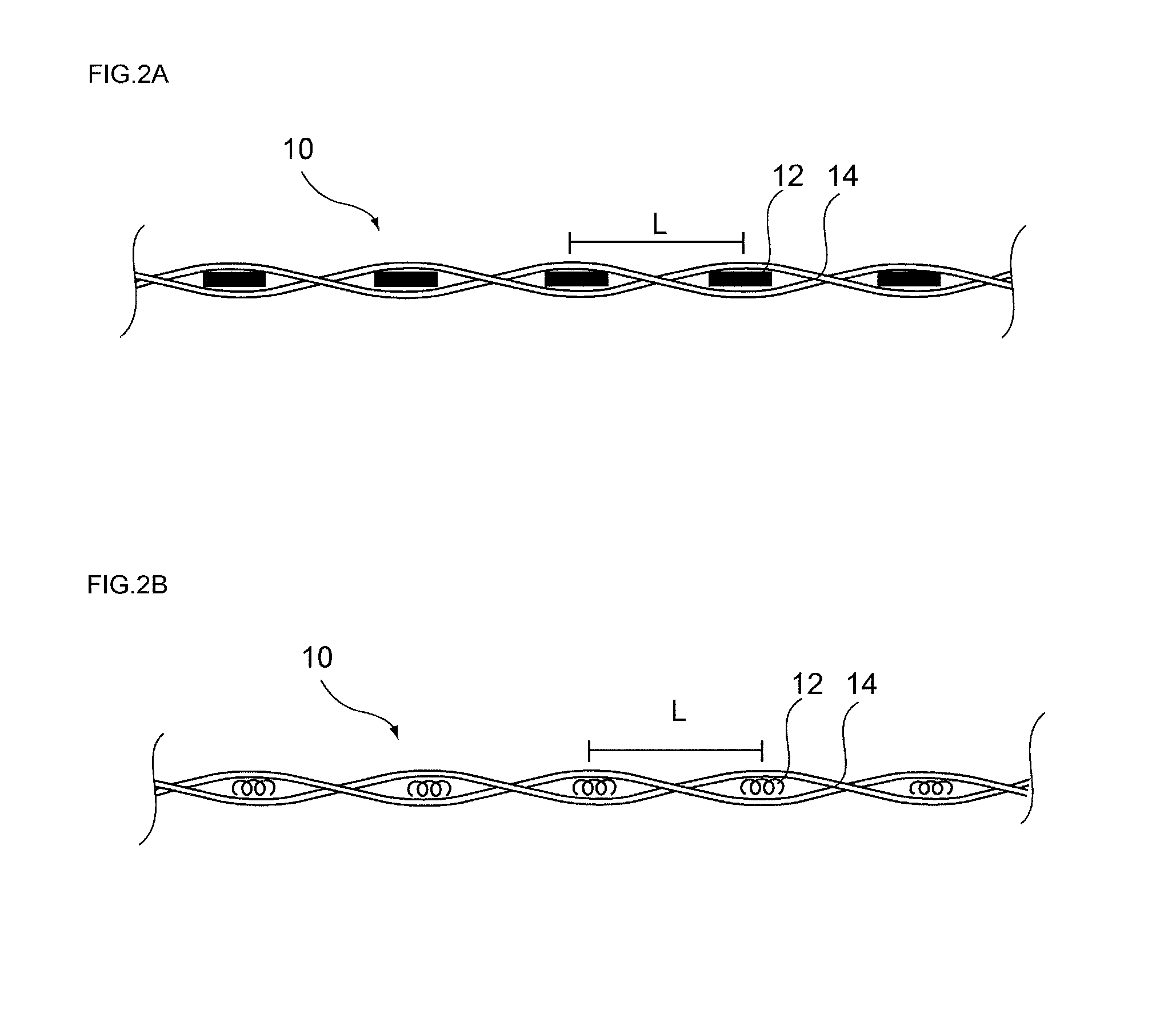
[0211]As shown in FIG. 4B, a 100 μm thick rayon nonwoven fabric was previously folded in a V-shape, and steel wires (2 mm in length, 1 mm in diameter) as X-ray detectable materials were placed at predetermined intervals (25 mm) at the bottom of the V-shape, and surrounded and covered with rayon fibers, so that a long member was obtained.
[0212]Subsequently, an aluminum foil (20 μm in thickness) provided with a polyvinyl chloride-based hot melt adhesive, and an absorbent pad (1.5 mm in thickness, 150 g / m2 in weight per area, 0.075 g / cm3 in bulk density) including rayon and polyester fibers and having a network polyethylene film on one side were stacked and subjected to heat and pressure bonding at about 110° C. to form a heat and pressure bonded laminate.
[0213]Using a cutter, the heat and pressure bonded laminate was then cut into pieces of a predetermined shape (25 mm in length, 13...
PUM
 Abstract
Description
Claims
Application Information
 - R&D
- Intellectual Property
- Life Sciences
- Materials
- Tech Scout
- Unparalleled Data Quality
- Higher Quality Content
- 60% Fewer Hallucinations
Browse by: Latest US Patents, China's latest patents, Technical Efficacy Thesaurus, Application Domain, Technology Topic, Popular Technical Reports.
© 2025 PatSnap. All rights reserved.Legal|Privacy policy|Modern Slavery Act Transparency Statement|Sitemap|About US| Contact US: help@patsnap.com