LED lighting

a technology of led lighting and led diodes, which is applied in the direction of semiconductor devices for light sources, lighting and heating apparatus, and use of semiconductor lamps. it can solve the problems of poor reliability, low thermal conductivity of implementation, and significant impact on the commercial viability of this product, and achieve the effect of compactness and energy saving

Active Publication Date: 2016-08-16
FILAMENT LIGHTING LLC
View PDF19 Cites 57 Cited by
  • Summary
  • Abstract
  • Description
  • Claims
  • Application Information

AI Technical Summary

Benefits of technology

[0008]Apparatus and associated methods relate to a diversion driver module that dynamically adds a diversion current to an LED current so that the summed current maintains a predetermined minimum holding current requirement of a phase-controlled dimmer supply. In an illustrative example, the diversion current may be a function of input AC line voltage and/or firing angle of the phase-controlled dimmer supply. The phase controlled device may include, for example, a triac. The triac may supply adj

Problems solved by technology

The removal of these components may have allowed it to mechanically fit into the base but will significantly impact the commercial viability of this product as it violates multiple standards, cannot dim, and will exhibit poor reliability.
For small bases including E10, E12 or E14, this is a particular challenge.
Such an implementation exhibits very low thermal conductivity.
However this orientation presents 2 problems: (i) difficulty for potting; and, (ii) long thermal path required for the conduction of heat from electronics components to the base cap resulting in higher thermal resistance.
If the PCB is left isolated from the base cap, the heat must dissipate first into the surrounding air with a very poor conductivity of 0.026 W/m-K.
In one embodiment, potting is dispensed from the top of the E12, but the flow is immediately impeded by the PCB making the process not suitable for high volume manufacturing.
Potting must be dispensed to fill the entire bottom screw portion so it can then cover the top of the PCB without entering the potting free zone, a very difficult task.
Even if it were possible to dispense the potting material, the geometry is inherently not optimal for thermals.
Less potting material is needed, saving cost and time needed to dispense the material into the base.
However, such sleeving may be difficult to control in overall size, as it may impede the flow of potting compound, and may also impedes heat flow from the

Method used


Image

  • LED lighting
  • LED lighting
  • LED lighting

Examples


example 1

[0060 of Prior Art Implementation of FIGS. 2-3

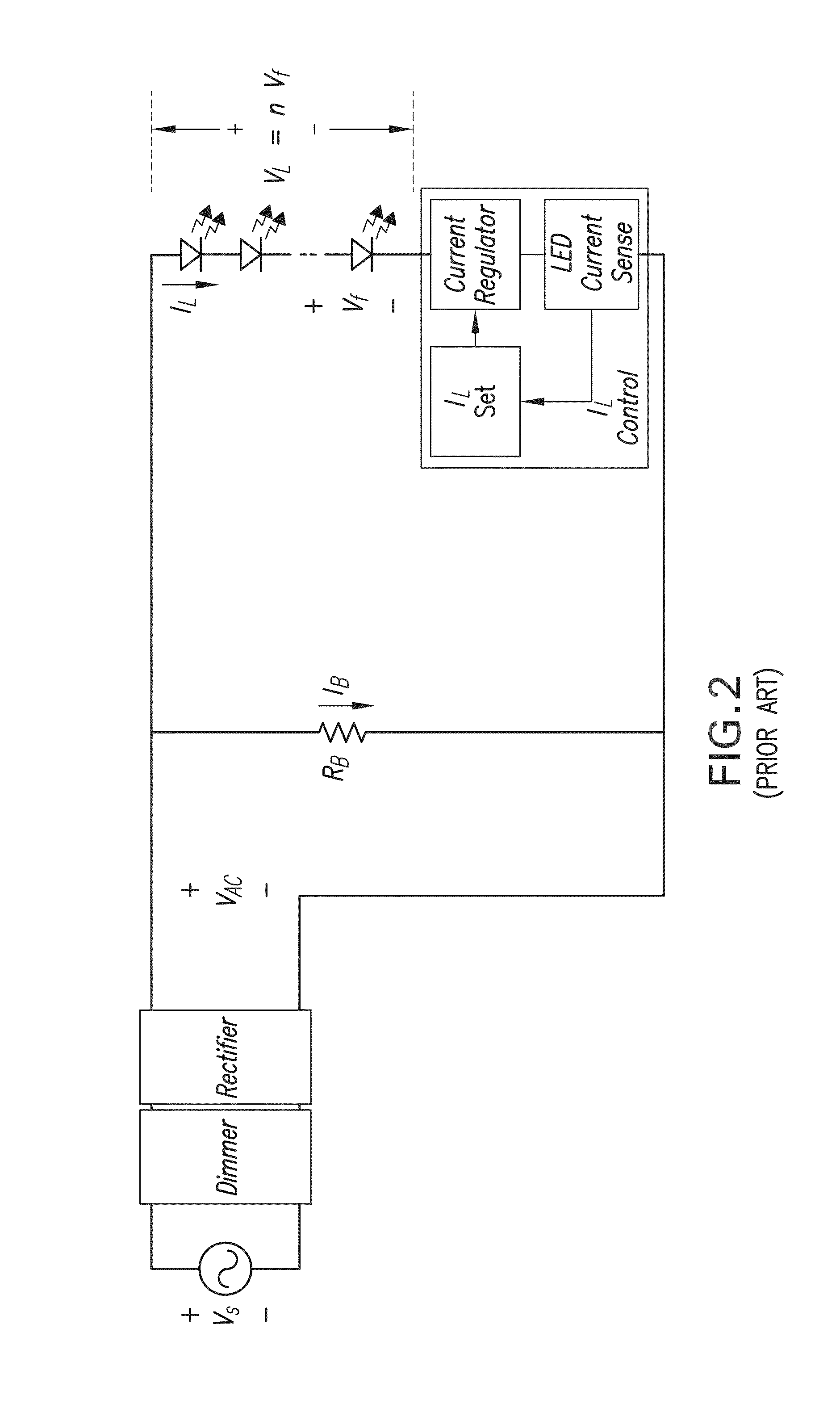
[0061]FIG. 2 shows a prior art implementation using a simple resistor RB to provide diversion current. However the diversion current is not constant and varies with the rectified AC line voltage VAC. The resulting current voltage waveforms are shown in FIG. 3.

[0062]To facilitate discussion and aid understanding, the following terms as used herein are described:

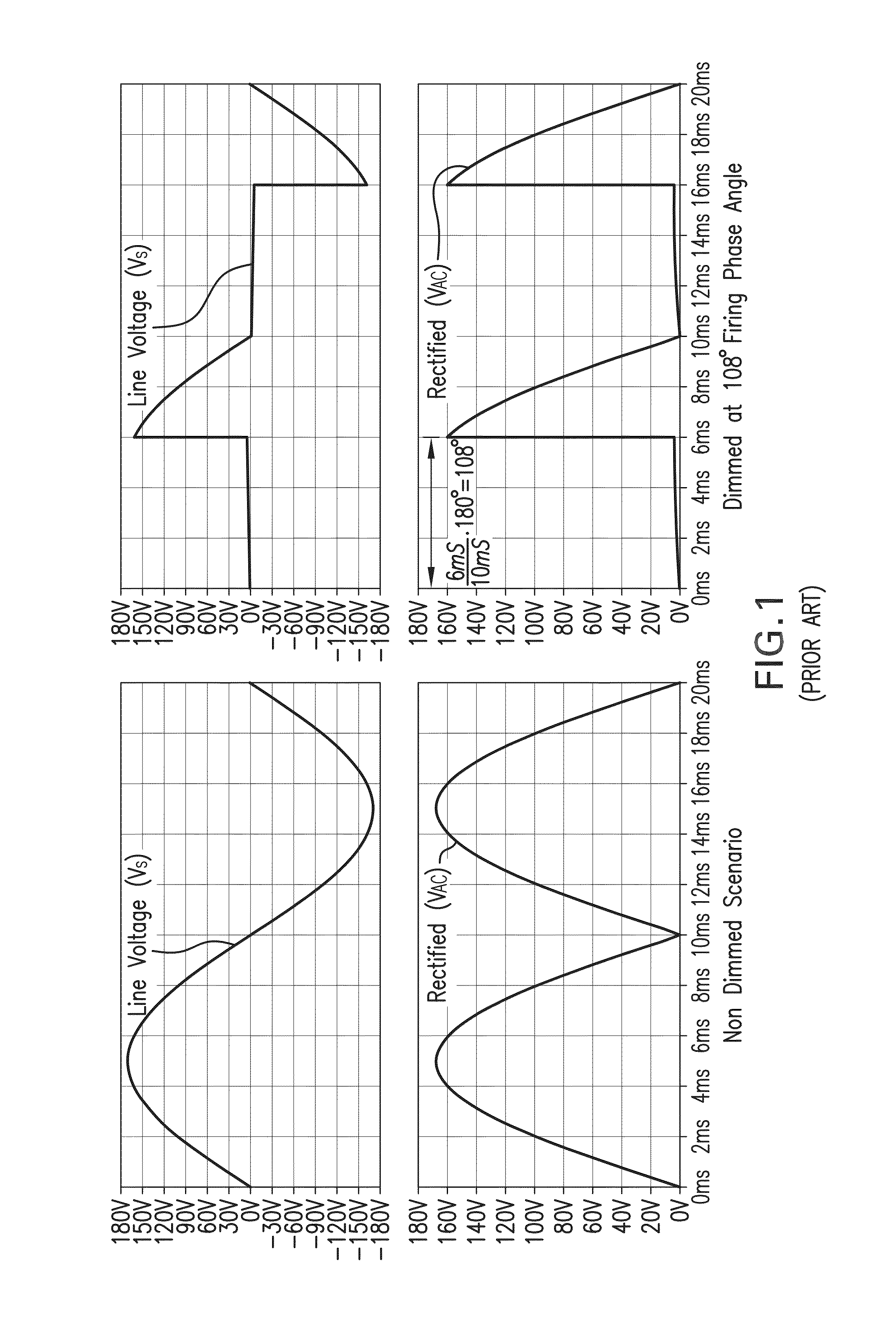
[0063]VS Input AC line voltage. Some common input voltage include 100 VAC, 110 VAC, 120 VAC, 230 VAC, 240 VAC, 277 VAC, 12 VAC, 24 VAC, 8 VAC, etc. For the examples in this document, VS=120 VAC @ 50 Hz. Although 50 Hz is used to simplify some exemplary calculations, the principles may be applied to other utility line voltages and frequencies, such as 60 Hz in North America.

[0064]VAC Rectified line voltage VS.

[0065]RB, IB Resistor and current for the bleeder circuit. For example, to set IB to 30 mA when VAC=60V, this requires RB=2000Ω.

[0066]n, Vf n is the number of individual LEDs e...

example 2

[0073 of Prior Art Implementation of FIGS. 4-5

[0074]FIG. 4 shows a prior art improved implementation using a current regulator and a resistor RB in the diversion current path. Efficiency is improved since the bleeder current IB is fixed after VAC reaches a certain value. The resulting current voltage waveforms are shown in FIG. 5.

[0075]In this example, bleeder circuit current is regulated to a constant value of IB=30 mA, once VAC>IB·RB or VAC>60V.

[0076]One implementation of such IB regulation circuit would be a linear regulator. The efficiency of such a circuit increases from 21% to 42%.

[0077]The table below shows examples of the maximum required triac hold up currents for a population of commercially available triacs, whether they are used in a lamp dimming system or not, from the Mouser Online website. As can be seen, small hold up currents, e.g., IHH>12 mA is desired for some minimum level compatibility. From actual testing, IH>15 mA may be, for some implementations, a minimum pr...


PUM


Abstract

Apparatus and associated methods relate to a diversion driver module that dynamically adds a diversion current to an LED current so that the summed current maintains a predetermined minimum holding current requirement of a phase-controlled dimmer supply. In an illustrative example, the diversion current may be a function of input AC line voltage and/or firing angle of the phase-controlled dimmer supply. The phase controlled device may include, for example, a triac. The triac may supply adjustable pulse-width current to dim the LED according to a phase control signal. The diversion driver module may include one or more heat dissipating components disposed in thermal communication with the lamp base. Some driver modules may be sufficiently compact and energy efficient to provide smooth dim-to-black performance while operating within acceptable temperature limits for reliable operation while contained in the base of a standard form factor lamp, such as an E12 full-glass lamp.

Description

CROSS-REFERENCE TO RELATED APPLICATIONS[0001]This application claims the benefit of U.S. Provisional Application Ser. No. 62 / 141,010, titled “LED Lighting,” filed by Shum, on Mar. 31, 2015. This application incorporates the entire contents of the foregoing application herein by reference.TECHNICAL FIELD[0002]Various embodiments relate generally to dimmable LED (light emitting diode) lighting sources, and some embodiments relate particularly to highly efficient compensated LED driver systems retrofittable to operate with existing phase-controllable sources that require a minimum holding current to maintain forward current conduction during dimming.BACKGROUND[0003]A significant portion of established, conventional lighting systems that convert electrical energy to light using incandescent or fluorescent technologies. These two well-established technologies offer well known trade-offs. Many buildings and structures have existing (e.g., legacy) lighting systems. Some of these systems ma...

Claims


Application Information

Patent Timeline
IPC IPC(8): H05B37/02H05B33/08F21V23/00F21K99/00F21V23/06H05B44/00
CPCH05B33/0812H05B33/0845F21V23/004H05B33/0824F21K9/1355F21V23/06F21V23/006F21K9/232F21Y2115/10F21K9/238F21V29/74H05B45/395H05B45/44H05B45/10H05B45/3575H05B45/20Y02B20/30H05B45/3725H05B45/56F21V29/713F21V29/773F21V29/83F21K9/65F21K9/68F21K9/235F21V23/005F21V29/75F21V29/763F21V29/80F21V29/81F21V3/00F21V23/003
Inventor SHUM, FRANK
Owner FILAMENT LIGHTING LLC
Why Eureka
Try Eureka