Current type D/A converter, delta sigma modulator, and communications device

a technology of deltasigma modulator and converter, applied in the field of current type d/a converter, deltasigma modulator, communication device, can solve the problems of increasing noise, reducing the effectiveness of dwa leveling technique, etc., to reduce the magnitude of variation, reduce the occurrence of harmonic distortion, and reduce the variation in the error-representing electric charge

Active Publication Date: 2016-09-06
SOCIONEXT INC
View PDF14 Cites 2 Cited by
  • Summary
  • Abstract
  • Description
  • Claims
  • Application Information

AI Technical Summary

Benefits of technology

[0012]According to the first aspect of the present disclosure, the control circuit controls the ON/OFF state of the first switch responsive to a digital input signal, and controls the ON/OFF state of the second switch in accordance with the control of the ON/OFF state of the first switch. For example, review a case where, in a situation where the ON/OFF state of the first switch is controlled by changing the level of the digital output signal, the quantity of electric charge representing an error (hereinafter referred to as “error-representing electric charge”) varies due to the use of the plurality of the D/A converter elements. Even in such a case, the control circuit allows for controlling, in accordance with the control of the ON/OFF state of the first switch, the ON/OFF state of the second switch so as to reduce the variation in the error-representing electric charge. That is because the second switch is configured to switch the electrical connection and disconnection between the capacitive load and the output node, and thus, the control of the ON/OFF state of the second switch allows for varying the error-representing electric charge. This allows for reducing the magnitude of variation in the sum of the electric charges output from the current type D/A converter (the sum of the quantities of the error-representing electric charge and the electric charge produced by the capacitive load). That is to say, t...

Problems solved by technology

Although the Bi-DWA technique as disclosed in U.S. Pat. No. 6,522,277, for example, allows for reducing the harmonic distortion, such a...

Method used


Image

  • Current type D/A converter, delta sigma modulator, and communications device
  • Current type D/A converter, delta sigma modulator, and communications device
  • Current type D/A converter, delta sigma modulator, and communications device

Examples


application example

[0093](Application Example)

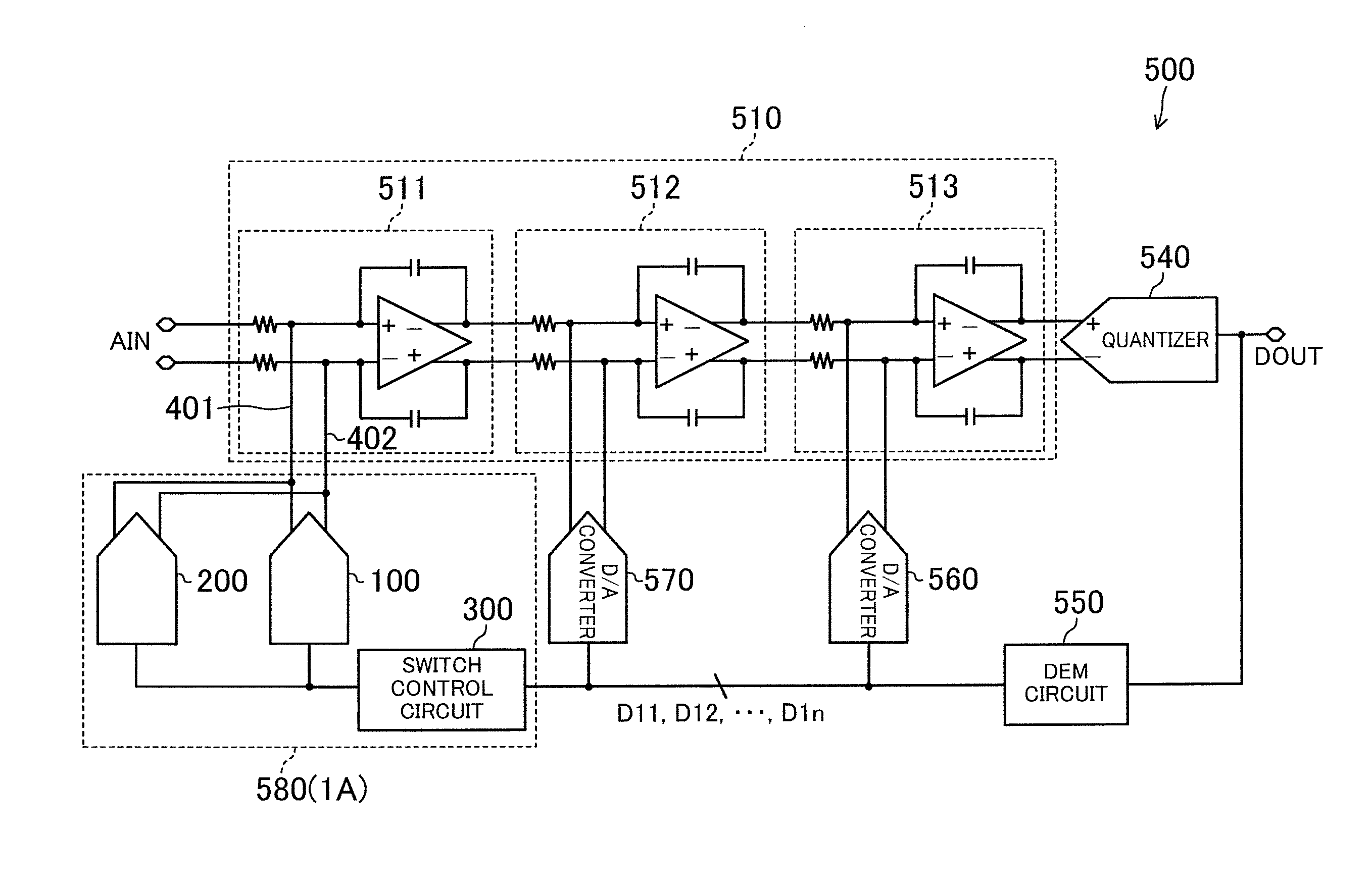
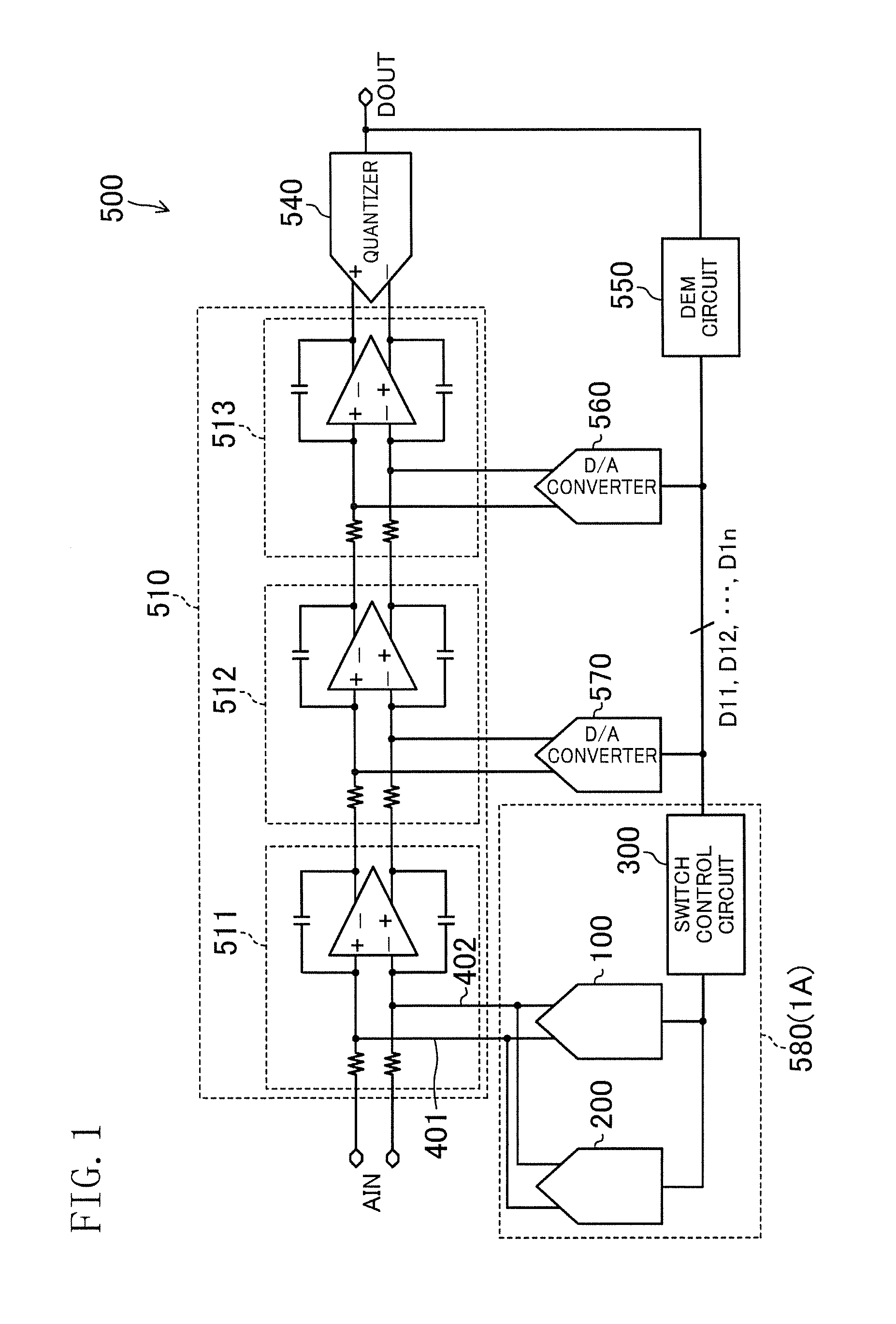
[0094]FIG. 11 is a block diagram illustrating an example configuration of a communications device 600 including the D / A converter 1A and the delta-sigma modulator 500 according to the present disclosure.

[0095]The communications device 600 of FIG. 11 includes: an antenna 610 by which a radio wave is received / transmitted; a transmitter 630 configured to perform a predetermined transmission process including a modulation process on a signal to be transmitted; a receiver 640 configured to perform a predetermined reception process including a decoding process on a received signal; and a duplexer 620 configured to perform switching between the signal to be transmitted and the received signal.

[0096]The receiver 640 includes a low noise amplifier (LNA) 641, a mixer 642, a low-pass filter 643, a delta-sigma modulator 644 according to any of the embodiments described above (e.g., the delta-sigma modulator 500 illustrated in FIG. 2), and a digital baseband processor ...


PUM


Abstract

This D/A converter includes a plurality of D/A converter elements, each comprising current sources configured to supply output currents to output nodes, and first switches configured to control the output currents. The output nodes are connected to a capacitor section having second switches and a capacitive load. The D/A converter further includes a switch control circuit configured to control the first switches responsive to digital signals, and also control the second switches in accordance with the control of the ON/OFF state of the first switches.

Description

CROSS-REFERENCE TO RELATED APPLICATIONS[0001]This is a continuation of International Application No. PCT / JP2014 / 001920 filed on Apr. 2, 2014, which claims priority to Japanese Patent Application No. 2013-145820 filed on Jul. 11, 2013. The entire disclosures of these applications are hereby incorporated by reference.BACKGROUND[0002]The present disclosure relates to a current type digital-to-analog (D / A) converter and a delta-sigma modulator including such a D / A converter, and particularly relates to a technique for reducing occurrence of harmonic distortion.[0003]It general, it is known that analog-to-digital (A / D) converters for use in delta-sigma modulators achieve, by noise shaping and oversampling techniques, higher precision and lower power dissipation than Nyquist A / D converters do. Among various types of delta-sigma modulators, a continuous-time delta-sigma modulator has been known as a tool suitably used to realize high-speed and broadband operation. In a continuous-time delt...

Claims


Application Information

Patent Timeline
IPC IPC(8): H03M3/00H03M1/06H03M1/08H03M1/74
CPCH03M3/502H03M1/0656H03M1/0863H03M1/745H03M1/742H03M3/464
Inventor MITANI, YOSUKEMORIE, TAKASHIMATSUKAWA, KAZUOUCHIDA, MASASHI
Owner SOCIONEXT INC
Why Eureka
Try Eureka