
Polarizing plate and image display device comprising same

a technology of polarizing plate and image display device, which is applied in the direction of polarizing elements, thin material handling, instruments, etc., can solve the problems of slow curing rate, limited thinness and light weight of liquid crystal device, and difficulty in maintaining protective film thickness at 20 m, etc., to achieve excellent water resistance, excellent adhesion, and high glass transition temperature

Active Publication Date: 2016-09-13
SHANJIN OPTOELECTRONICS (NANJING) CO LTD
View PDF10 Cites 6 Cited by
  • Summary
  • Abstract
  • Description
  • Claims
  • Application Information

AI Technical Summary

Benefits of technology

[0030]The polarizing plate of the present invention has excellent adhesion between a polarizer and a protective layer, is excellent in water resistance such that discoloration of the polarizer does not occur even under a high humidity environment, has a high glass transition temperature after curing of a radical curable composition for forming a protective layer, and thus is excellent in heat resistance.
[0031]Further, the polarizing plate of the present invention has a protective layer having a small thickness as compared to a polarizing plate having a transparent protective film in the related art, and thus may be manufactured as a thin-type.MODE FOR INVENTION
[0032]Hereinafter, preferred exemplary embodiments of the present invention will be described. However, the exemplary embodiments of the present invention may be modified in various forms, and the scope of the present invention is not limited to the exemplary embodiments which will be described below. Further, exemplary embodiments of the present invention are provided to more completely explain the present invention to a person with ordinary skill in the art.1. Polarizing Plate
[0033]As a result of repeated studies, the present inventors have found that when a radical curable compound having two or more of each of a benzene ring, a (meth)acryloyl group and a carboxyl group in a molecule thereof is used in mixture with an acrylic compound having a hydroxy group, and the like in a radical curable composition for forming a protective layer, water resistance and heat resistance are very excellent, thereby completing the present invention.
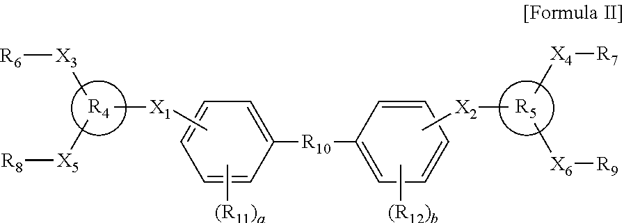
[0034]More specifically, the present invention is a polarizing plate including a polarizer, and a protective layer formed on at least one surface of the polarizer, in which the protective layer is a cured product of a radical curable composition including (A) a first compound represented by the following [Formula 1], (B) a radical curable second compound having two or more of each of a benzene ring, a (meth)acryloyl group, and a carboxyl group in a molecule thereof, and (C) a radical initiator.
[0036]In [Formula I], R1 is an ester group or an ether group; R2 is a C1˜10 alkyl group, a C4˜10 cycloalkyl group, or a combination thereof, and in this case, R2 has at least one hydroxy substituent in a molecule thereof; and R3 is hydrogen, or a substituted or unsubstituted C1˜10 alkyl group.1-1. Polarizer

Problems solved by technology

However, in a polarizing plate in which a TAC film and the like are laminated as the protective film as described above, it is difficult to maintain a thickness of the protective film at 20 μm or less from the viewpoint of handling property or durability performance during the operation, so that there is a limitation for the liquid crystal device to be thin and light weight.
In this case, when a transparent thin film layer is formed using a cationic curable composition, there is an advantage in that excellent adhesion with the polarizer is achieved, but there are many disadvantages in the manufacturing process due to a slow curing rate and a low degree of curing.
However, in the case of a radical curable composition including an acrylic compound as a main component, there are problems in that the curing rate is fast compared to a cationic curable composition, while the glass transition temperature of a protective layer after curing of the radical is low, such that heat resistance reliability of a polarizing plate to be manufactured using the same is not good.
However, when these are additionally added, the glass transition temperature of the radical curable composition may be increased, but since there is an aspect in which water resistance which a polarizing plate needs to basically have becomes considerably reduced, the addition of these compounds has been fatally disadvantageous in application to the polarizing plate.

Method used


Image

  • Polarizing plate and image display device comprising same
  • Polarizing plate and image display device comprising same
  • Polarizing plate and image display device comprising same

Examples


preparation example 1

Manufacture of Acrylic Protective Film

[0094]A raw material pellet was manufactured by supplying a resin composition, in which poly(N-cyclohexylmaleimide-co-methylmethacrylate), a styrene-maleic acid anhydride copolymer resin and a phenoxy-based resin were uniformly mixed with each other at a weight ratio of 100:2.5:5, to a 24Φ extruder in which a portion from a raw material hopper to the extruder was substituted with nitrogen, and melting the mixed resin composition at 250° C.

[0095]PKFE (Mw=60,000, Mn=16,000, Tg=95° C.) manufactured by InChemRez® Co., Ltd., was used as the phenoxy-based resin, Dylaeck 332 with a content of 85 wt % of styrene and 15 wt % of anhydrous maleic acid anhydride was used as the styrene-maleic acid anhydride copolymer resin, and as the poly(N-cyclohexylmaleimide-co-methylmethacrylate) resin, a resin with a content of 6.5 wt % of N-cyclohexylmaleimide as a result of NMR analysis was used.

[0096]The obtained raw material pellet was dried under vacuum, melted by...

preparation example 2

Preparation of Radical Curable Composition

[0098](1) Radical Curable Composition A

[0099]Radical curable composition A was prepared by mixing 3 parts by weight of a radical initiator Irgacure-819 (manufactured by Ciba Specialty Chemicals Co., Ltd.) with 100 parts by weight of a resin composition prepared by mixing 50 parts by weight of 2-hydroxyethylacrylate with 50 parts by weight of a compound represented by the following [Formula 11].

[0100]

[0101](2) Radical Curable Composition B

[0102]Radical curable composition B was prepared by mixing 3 parts by weight of a radical initiator Irgacure-819 (manufactured by Ciba Specialty Chemicals Co., Ltd.) with 100 parts by weight of a resin composition prepared by mixing 50 parts by weight of 2-hydroxyethylacrylate with 50 parts by weight of a compound represented by the following [Formula 12].

[0103]

[0104](3) Radical Curable Composition C

[0105]Radical curable composition C was prepared by mixing 3 parts by weight of a radical initiator Irgacure-8...

example 1

[0113]Radical curable composition A was applied on a primer layer of an acrylic film-based protective film prepared in Preparation Example 1 by using a dropper, and lamination was performed on one surface of a polarizer (PVA device), a condition was set such that the thickness of the final adhesive layer became 1 to 2 μm, and then the film was allowed to pass through a laminator (5 m / min). Then, a polarizing plate including a protective film on one surface of a polarizer was manufactured by irradiating UV light with 900 mJ / cm2 on a surface, on which the acrylic film was laminated, using a UV irradiation device (fusion lamp, D bulb).

[0114]Next, Radical curable composition A was applied on the other surface of the side of the PVA device of the polarizing plate manufactured on which the protective film was laminated, a PET film having a release force was laminated, a condition was set such that the thickness of the final protective layer became 5 to 6 μm, and then the film was allowed ...


PUM

PropertyMeasurementUnit
acid valueaaaaaaaaaa
glass transition temperatureaaaaaaaaaa
thicknessaaaaaaaaaa

Abstract

The present invention relates to a polarizing plate including a polarizer; and a protective layer formed on at least one surface of the polarizer, in which the protective layer is a cured product of a radical curable composition including (A) a first compound represented by [Formula 1], (B) a radical curable second compound having two or more of each of a benzene ring, a (meth)acryloyl group, and a carboxy group in a molecule thereof, and (C) a radical initiator, and an image display device including the same.

Description

[0001]This application is a National Stage Application of International Application No. PCT / KR2014 / 008724, filed Sep. 19, 2014, and claims the benefit of Korean Application No. 10-2013-0116991, filed Sep. 30, 2013, and Korean Application No. 10-2014-0121321, filed Sep. 12, 2014, all of which are hereby incorporated by reference in their entirety for all purposes as if fully set forth herein.TECHNICAL FIELD[0002]The present invention relates to a polarizing plate and an image display device including the same, and more specifically, to a polarizing plate which has excellent adhesion between a polarizer and a protective layer, is excellent in water resistance and heat resistance, and may be manufactured as a thin-type, and an image display device including the same.BACKGROUND ART[0003]A polarizing plate has been usually used in a structure, in which a protective film is stacked on both surfaces of a polarizer formed of a polyvinyl alcohol (hereinafter, referred to as ‘PVA’)-based resi...

Claims


Application Information

Patent Timeline
Patent Type & Authority Patents(United States)
IPC IPC(8): C09K19/00G02B1/14G02B5/30
CPCG02B1/14G02B5/3033Y10T428/10Y10T428/105Y10T428/1036Y10T428/1041C09K2323/00C09K2323/03C09K2323/031C09K2323/035G02B5/30G02F1/1335
Inventor PARK, KWANG-SEUNGLEE, MI-RINPARK, JUN-WUKHUH, EUN-SOO
Owner SHANJIN OPTOELECTRONICS (NANJING) CO LTD
Learn More