
Safety device for installation in a gas-supply system, in particular, an acetylene-supply system

a safety device and gas supply technology, applied in the direction of fluid pressure control, functional valve types, gas/liquid distribution and storage, etc., can solve the problems of valve destruction, valve replacement, and inability to reliably reproduce closing behavior, etc., to achieve high level of operational reliability and compact structur

Active Publication Date: 2016-09-20
SPECTRON GAS CONTROL SYST
View PDF13 Cites 0 Cited by
  • Summary
  • Abstract
  • Description
  • Claims
  • Application Information

AI Technical Summary

Benefits of technology

The invention is a safety device for a gas-supply system, specifically an acetylene-supply system. It is designed to be compact and highly reliable, with no need for additional valves. The control valve and over-pressure valve are preassembled and encapsulated, ensuring accurate functioning and reproducible performance. This design also makes it easier to replace the whole module, instead of individual components. The technical effects of this invention include a higher level of operational reliability, compact design, and high safety standards.

Problems solved by technology

However, the discharge of acetylene to a secure location is still associated with danger and environmental pollution; therefore, it is fundamentally undesirable (EN ISO 14114:1999, Section 4.1.1.f).
The quick-action valve does have a simple construction, but it also comes with disadvantages, one being that the closing behavior cannot be reliably reproduced and another that the valve is destroyed when used and has to be removed and replaced before the gas-supply equipment can be operated again.
Another basic problem associated with reliably supplying acetylene gas is that the pressure regulator's outlet pressure is subject to a certain degree of uncertainty too.
If the inlet pressure rises, for example, due to an acetylene decomposition reaction, there is a risk of the valve opening and destroying the pressure-limiting device as a result.
This interrupts any further gas supply.
The pressure thus remaining in the over-pressure chamber acts together with the spring on the closing element in the closing direction and prevents the over-pressure valve from opening again, or makes this process difficult.
If the safety valve has been activated, i.e., the gas supply has been unavoidably interrupted due to the limit value for the outlet pressure being exceeded or the limit value for the inlet pressure being exceeded, the rear pressure chamber is subject to over-pressure.
It is not possible to continue using the safety device in this condition; it must be removed or—ideally—vented.
A high pressure makes it difficult to actuate the closing element.
The encapsulation prevents unauthorized access to the cartridge and the predefined settings being changed, or makes these actions difficult.

Method used


Image

  • Safety device for installation in a gas-supply system, in particular, an acetylene-supply system
  • Safety device for installation in a gas-supply system, in particular, an acetylene-supply system
  • Safety device for installation in a gas-supply system, in particular, an acetylene-supply system

Examples


example 1

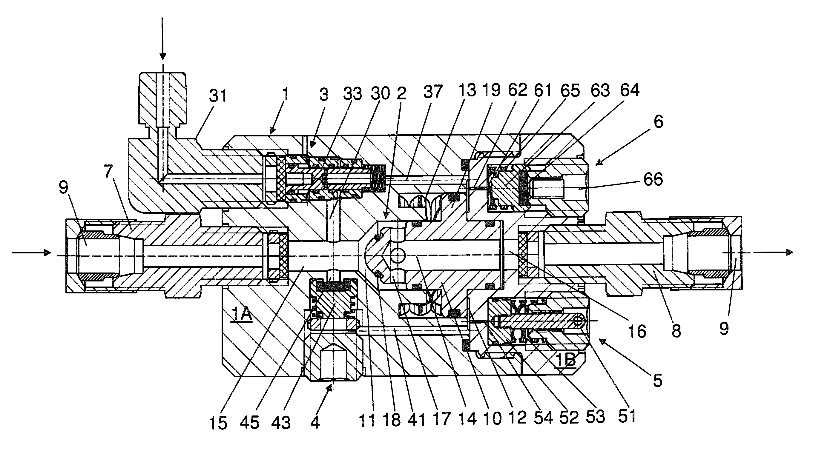
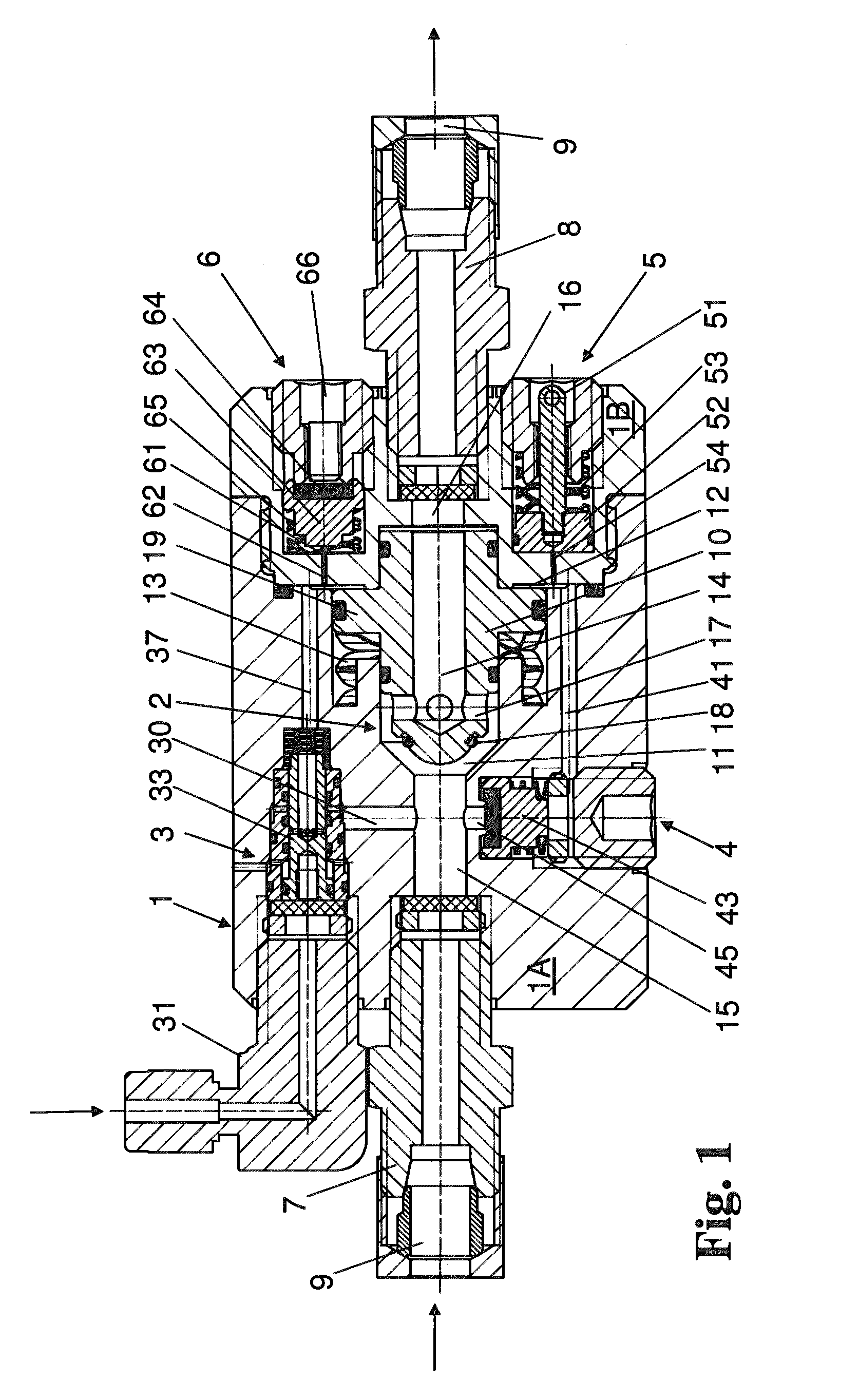
[0071]The embodiment of the safety device depicted in FIG. 1 is designed for installation in the supply line of an acetylene system in which acetylene is drawn from cylinders or cylinder bundles. The safety device is designed as a multiple unit valve and is installed in the system's high-pressure area—upstream of the main pressure regulator.

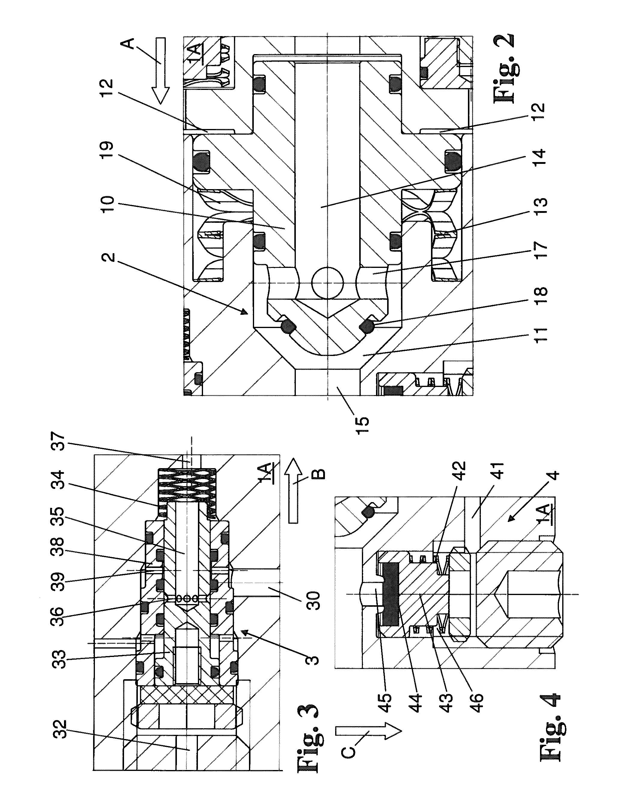
[0072]The valve body 1 consists of a two-part, essentially monolithic brass block. Both block parts (housing 1A and housing cover 1B) are screwed together and sealed. Sealing elements are basically depicted in FIGS. 1 to 4 as black surface entities. The valve body 1 features a number of holes, which accommodate the following components: a safety valve 2 (stop valve), a control valve 3, an over-pressure valve 4, a display instrument 5, and a vent valve 6.

Safety Valve 2

[0073]The valve body 1 has a central through hole, into which the gas connections 7; 8, which serve to connect the safety device to the acetylene supply line, are screwed on both sid...

example 2

[0096]An embodiment of the safety device invention modified from that depicted in FIG. 1 is explained below based on FIGS. 5 to 11. As can be seen from the figures, this embodiment features a number of sealing rings arranged in pairs, whereby one of the two sealing rings in each case serves as the “sacrificial ring”. If this ring is destroyed through acetylene decomposition, the other sealing ring continues to guarantee the sealing function. Furthermore, some of the single valve units integrated in the valve body 1 have been designed as preassembled, self-contained units, or “cartridges”, which can be fitted and set at the factory.

[0097]These and other differences will be explained in more detail below. Inasmuch as the same reference numbers are used as in FIGS. 1 to 4, they refer to the same or equivalent components or parts of the safety device as have already been explained for the embodiment described in Illustration 1.

[0098]The safety device is designed for installation in the ...


PUM


Abstract

Relevant specifications in the field of gas supply provide for different safety devices for installation in a gas-supply system, in particular, an acetylene-supply system. To provide such a safety device, which is characterized by a compact structure and a high level of operational reliability, this invention proposes that a valve body (1) incorporates an over-pressure valve (4; 104) of a quick-action shut-off device, a control valve (3; 103) of a pressure-limiting device, and a safety valve (2; 102), whereby the safety valve (2; 102) can be fluidically connected to the over-pressure valve (4; 104) and the control valve (3; 103), and closes either when the over-pressure valve (4; 104) opens due to an inlet pressure that is above the inlet-pressure limit value or when the control valve (3; 103) opens due to an outlet pressure that is above an outlet-pressure limit value.

Description

TECHNICAL BACKGROUND[0001]The invention refers to a safety device for installation in a gas-supply system, in particular, an acetylene-supply system, where a main pressure regulator relieves gas fed in at inlet pressure to outlet pressure.[0002]In its simplest form, the gas-supply system can be a gas cylinder, a tank or another type of container. Several containers can also be connected to one another, so when one container becomes empty, the system is able to switch to a different container which is still full.[0003]The gas-supply system feeds the gas to a tapping point. The gas to be tapped is pressurized and in this respect already represents a certain hazard potential for users and the environment. In principle, the safety device is suitable for installation in all gas-supply systems of this type. However, it has a particularly beneficial effect when used with combustible or toxic gases, such as methane, propane, natural gas, hydrogen, liquid gas, carbon monoxide, halogens and s...

Claims


Application Information

Patent Timeline
Patent Type & Authority Patents(United States)
IPC IPC(8): G05D16/16F16K17/02F16K1/30F16K17/10F16K17/06F16K17/04G05D16/18F17C13/04F16K17/168G05D16/04
CPCG05D16/04F16K1/304F16K17/025F16K17/048F16K17/06F16K17/10F16K17/168F17C13/04G05D16/18F17C2205/0332F17C2205/0382F17C2205/0385Y10T137/7794Y10T137/7922Y10T137/877Y10T137/87756F16K17/32G05D16/187G05D16/163G05D16/166F16K17/065
Inventor VAN DER KLIFT, JOHANRONCKA, ANDREAS
Owner SPECTRON GAS CONTROL SYST
Learn More