Tubular conveyor belt or pocket conveyor belt having a chevron profile arrangement on the carrying side thereof

a technology of conveyor belts and chevrons, which is applied in the direction of conveyors, transportation and packaging, etc., can solve the problems of polluting the environment, posing a risk to the environment, and not being able to be carried out normally, so as to simplify the transportation of the conveyor belt, reduce production costs

Active Publication Date: 2016-10-11
CONTITECH TRANSPORTBANDSYSTEME GMBH
View PDF28 Cites 7 Cited by
  • Summary
  • Abstract
  • Description
  • Claims
  • Application Information

AI Technical Summary

Benefits of technology

[0011]It is an object of the present invention to provide a conveyor belt of the type described above which can be produced easily and cost-effectively and transported and can be used at the same time as a roller conveyor belt or pocket conveyor belt and allows higher gradients than those which have been known hitherto, that is, angles of inclination above 35° in gradient.
[0022]According to one aspect of the present invention, the width of the profiling corresponds essentially to the belt width between the peripheral zones. This means that the profiling takes up, as far as possible, the entire width between the overlapping peripheral zones in order, on the one hand, to leave the zones free and not to impair the overlapping or closing action of the tubular conveyor belt and, on the other hand, to retain as much conveyable material as possible via the profiling.
[0023]According to one aspect of the present invention, the width of the chevron profiling corresponds essentially to the belt width up to the horizontal of the closed pocket conveyor belt. This means that the profiling is formed over the width of the conveyor belt such that, in the case of the droplet-form pocket conveyor belt being closed, the profiling can retain conveyable material in the regions in which the conveyable material butts, as a result of gravitational force, against the carrying-side surface of the pocket conveyor belt. Above the horizontal, it is possible to dispense with the profiling because, here, the conveyable material butts rather against the conveyable material retained vertically beneath and less against the carrying-side surface of the pocket conveyor belt.
[0027]According to a further aspect of the present invention, the profiling has a plurality of individual diagonal elements, which are spaced apart from one another by an interruption and together extend both in the longitudinal direction and in the transverse direction of the conveyor belt to give, jointly, a V-shape, wherein the individual diagonal elements have a different orientation, preferably an orientation extending more in the longitudinal direction, to that of all of the adjacent diagonal elements taken as a whole. In this way, the closed V-shape is interrupted to give individual elements, and therefore the internal frictional forces of the conveyable material act at the interruptions and can thus retain the conveyable material on the conveyor belt. In other words, the contact surfaces with force-fitting action will increase as a result of the interspaces between the individual diagonal elements. If the individual diagonal elements are arranged at a steeper angle on the carrying side cover panel than all of the diagonal elements forming the V-shape, then it is also the case that those ends of the individual diagonal elements which are oriented in a conveying direction subject the conveyable material to a retaining action.
[0031]According to a further aspect of the present invention, the conveyor belt has at least one transverse reinforcement. This provides stability to the round shape of the rolled-together tubular conveyor belt, even in the case of the latter being used continually over a relatively long period of time. For this purpose, it is possible, for steel-cable conveyor belts and textile conveyor belts, to use both steel-cable transverse reinforcements and textile transverse reinforcements, both jointly and as alternatives.
[0032]According to a further aspect of the present invention, the chevron profiling is configured in the form of a constituent part of the carrying-side cover panel. This reduces the production costs and simplifies transportation of the conveyor belt.

Problems solved by technology

Since the conveyable material is open to the environment as it is being transported, contaminants and environmental weathering influences can act on the conveyable material, and the latter can pollute the environment and also pose a risk to the environment.
It is thus not usually possible, in conventional belt systems, to exceed an angle of inclination of 20° in gradient.
This increases the complexity for, and therefore the costs of, the conveyor system to a considerable extent.
It is also the case that the conveyable material cannot be influenced by the environment during transportation.
It is a disadvantage of the above-described tube belts or pocket belts that they involve very high outlay, and are therefore expensive to produce.
Furthermore, the adhesive-bonding locations constitute a weak point which, over time, will fail sooner than other constituent parts of the conveyor belt.
It is also disadvantageous that, if the known tube belts or pocket belts are suitable for relatively large angles of inclination, that is, above 35° in gradient, the conveyable material is retained in a form-fitting manner by the transverse strips and the latter are subjected to corresponding loading.
This requires a corresponding stable and radial formation of the transverse strips with higher material and production costs than in the case of flatter profilings, although the latter do not allow such gradients.
It is also the case that the higher transverse strips increase the transportation costs of the conveyor belts, because the latter cannot be wound as tightly for transportation purposes, that is, less belt length per rolled together belt drum can be transported in one journey.

Method used


Image

  • Tubular conveyor belt or pocket conveyor belt having a chevron profile arrangement on the carrying side thereof
  • Tubular conveyor belt or pocket conveyor belt having a chevron profile arrangement on the carrying side thereof
  • Tubular conveyor belt or pocket conveyor belt having a chevron profile arrangement on the carrying side thereof

Examples


Embodiment Construction

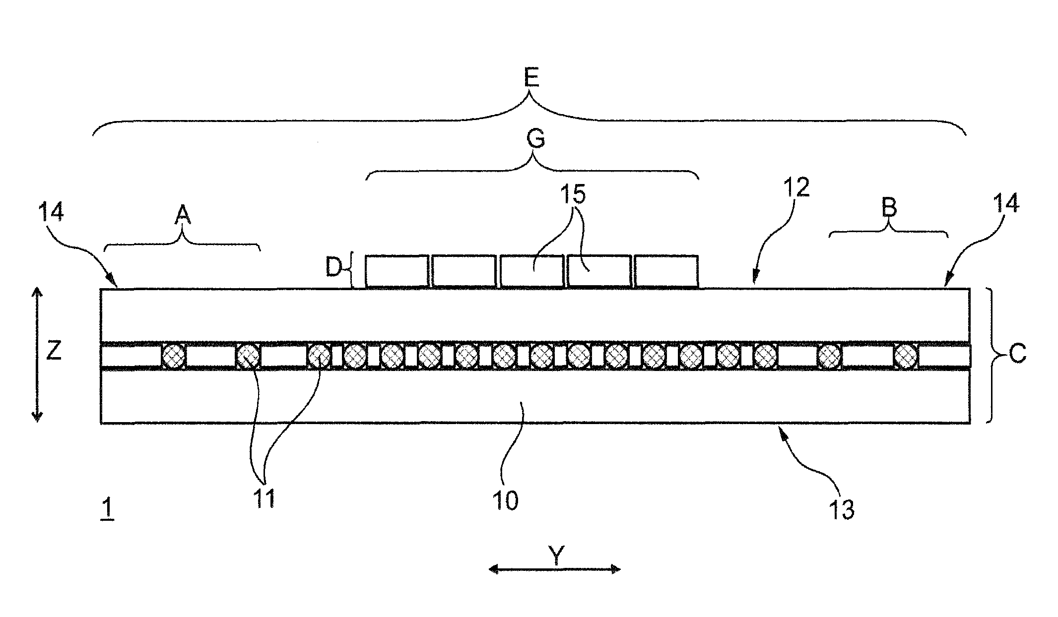
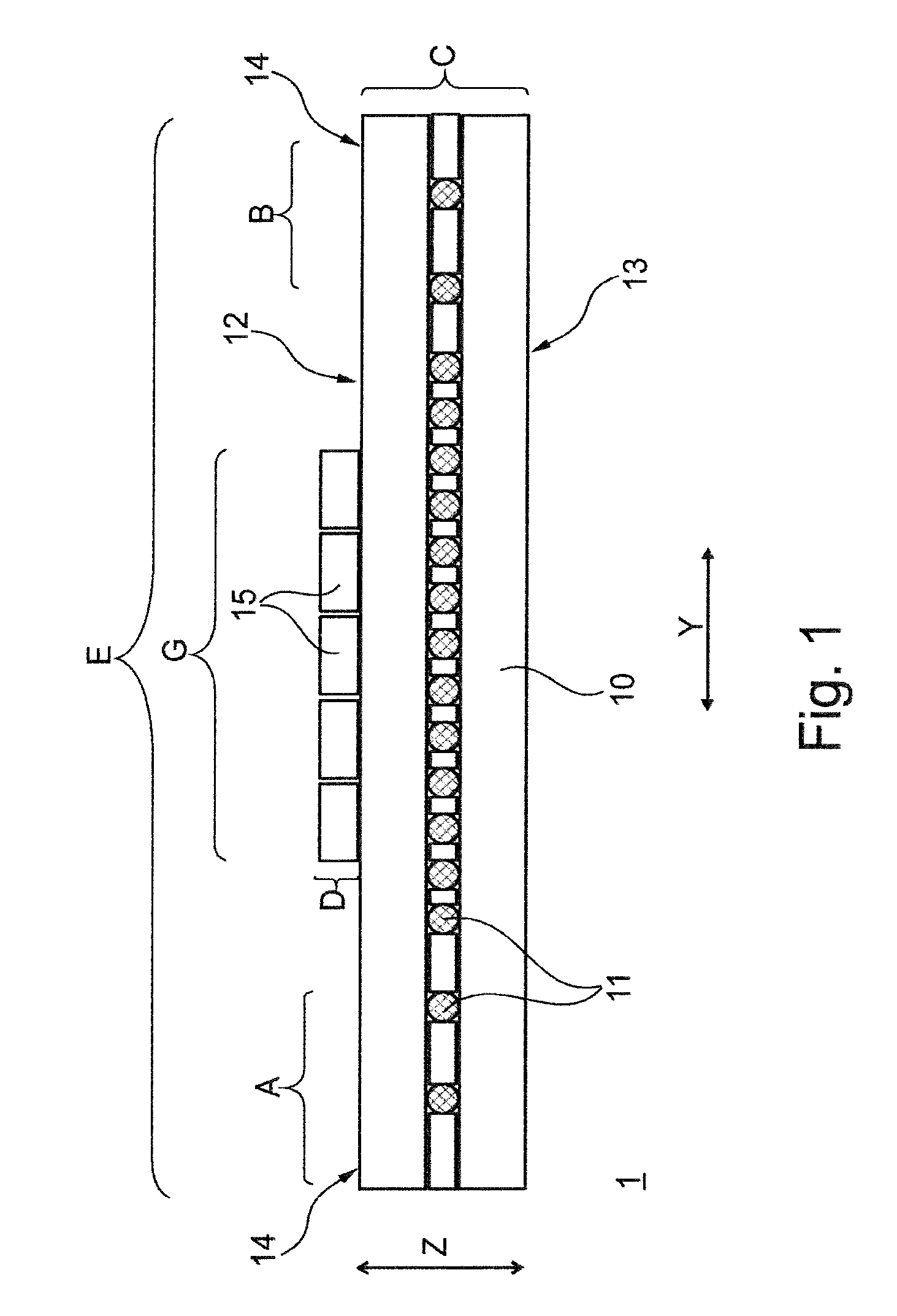
[0043]FIG. 1 shows a schematic illustration of a section through a conveyor belt 1 according to the invention. The conveyor belt 1 has a belt body 10, of width E in transverse direction Y, having a carrying-side cover panel 12 and a running-side cover panel 13. Reinforcement members 11 are embedded in the belt body 10, between the two cover panels (12, 13), the reinforcement members running in the longitudinal direction X (cf. FIGS. 3A and 3B) and absorbing the tensile forces of the conveyor belt 1. The reinforcement members 11, or also tension members 11, may be, for example, steel cables 11, in the case of steel-cable conveyor belts 1 (cf. FIG. 3A), or textiles 11 (cf. FIG. 3B) made of, for example, polyester, polyamide, cotton, et cetera, in the case of textile conveyor belts 1, or aramid 11 (not illustrated), in the case of aramid conveyor belts 1. The height C of the conveyor belt 1 extends in the direction Z, that is, perpendicularly to the transverse direction Y and longitudi...


PUM


Abstract

A conveyor belt includes a carrying-side cover plate and a running-side cover plate. The cover plates conjointly define a belt body having a plurality of reinforcement elements embedded therein. The belt body has edge zones and is closable so as to cause the edge zones to overlap and be in mutual contact engagement to form a tube conveyor belt or a pocket conveyor belt. The carrying-side cover plate has a chevron profile arrangement which includes a plurality of diagonal elements extending in both a longitudinal direction and a transverse direction of the conveyor belt. Each two of the diagonal elements conjointly defines a pair with multiple pairs defining a V-formation having a tip aligned in a direction opposite to the direction of movement of the belt.

Description

CROSS REFERENCE TO RELATED APPLICATIONS[0001]This application is a continuation application of international patent application PCT / EP2014 / 054296, filed Mar. 6, 2014, designating the United States and claiming priority from German application nos. 10 2013 104 595.2, filed May 6, 2013, and 10 2013 106 479.5, filed Jun. 21, 2013, and the entire content of each of the above applications is incorporated herein by reference.BACKGROUND OF THE INVENTION[0002]For the purpose of conveying loose materials such as bulk materials, that is, rock / stones, mineral resources, excavation material, agricultural products, et cetera, use has long been made of troughed conveyor belts, which receive the conveyable material at a receiving location on their carrying side and discharge the same at a discharge location. Since the conveyable material is open to the environment as it is being transported, contaminants and environmental weathering influences can act on the conveyable material, and the latter can...

Claims


Application Information

Patent Timeline
Patent Type & Authority Patents(United States)
IPC IPC(8): B65G17/04B65G15/08B65G15/40B65G15/42
CPCB65G15/42B65G15/08B65G15/40
Inventor MINKIN, ANDREY
Owner CONTITECH TRANSPORTBANDSYSTEME GMBH
Why Eureka
Try Eureka