Network for bone conduction transducers

a network and bone conduction technology, applied in the field of bone conduction transducer network, can solve the problems of poor input impedance, limited force output of hearing aids, poor high frequency gain in bone conduction applications, etc., and achieve the effect of increasing the force outpu

Active Publication Date: 2016-11-08
OSSEOFON AB
View PDF10 Cites 0 Cited by
  • Summary
  • Abstract
  • Description
  • Claims
  • Application Information

AI Technical Summary

Problems solved by technology

One problem with variable reluctance vibrators is that they have an input impedance which is predominately inductive especially at mid and high frequencies.
Since output force generation is current controlled this means that the high frequency gain in bone conduction applications are poor as it will be limited battery voltage which typically is only 1-1.5 Volt.
As a consequence, it is well known that bone-anchored hearing aids have a limited force output at mid and high frequencies and that they therefore have limited ability to compensate for a sensorineural hearing loss.
One drawback with this approach is that the output force at lower frequencies will be reduced as the capacitor blocks the signal.

Method used


Image

  • Network for bone conduction transducers
  • Network for bone conduction transducers
  • Network for bone conduction transducers

Examples


Embodiment Construction

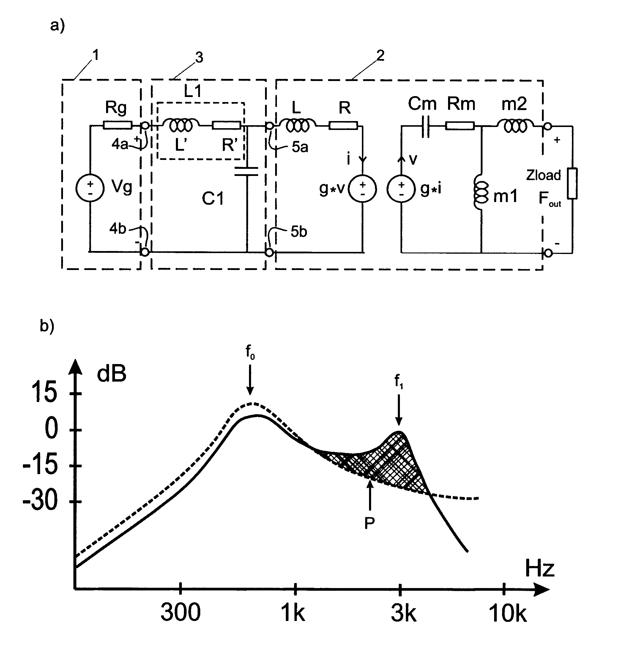
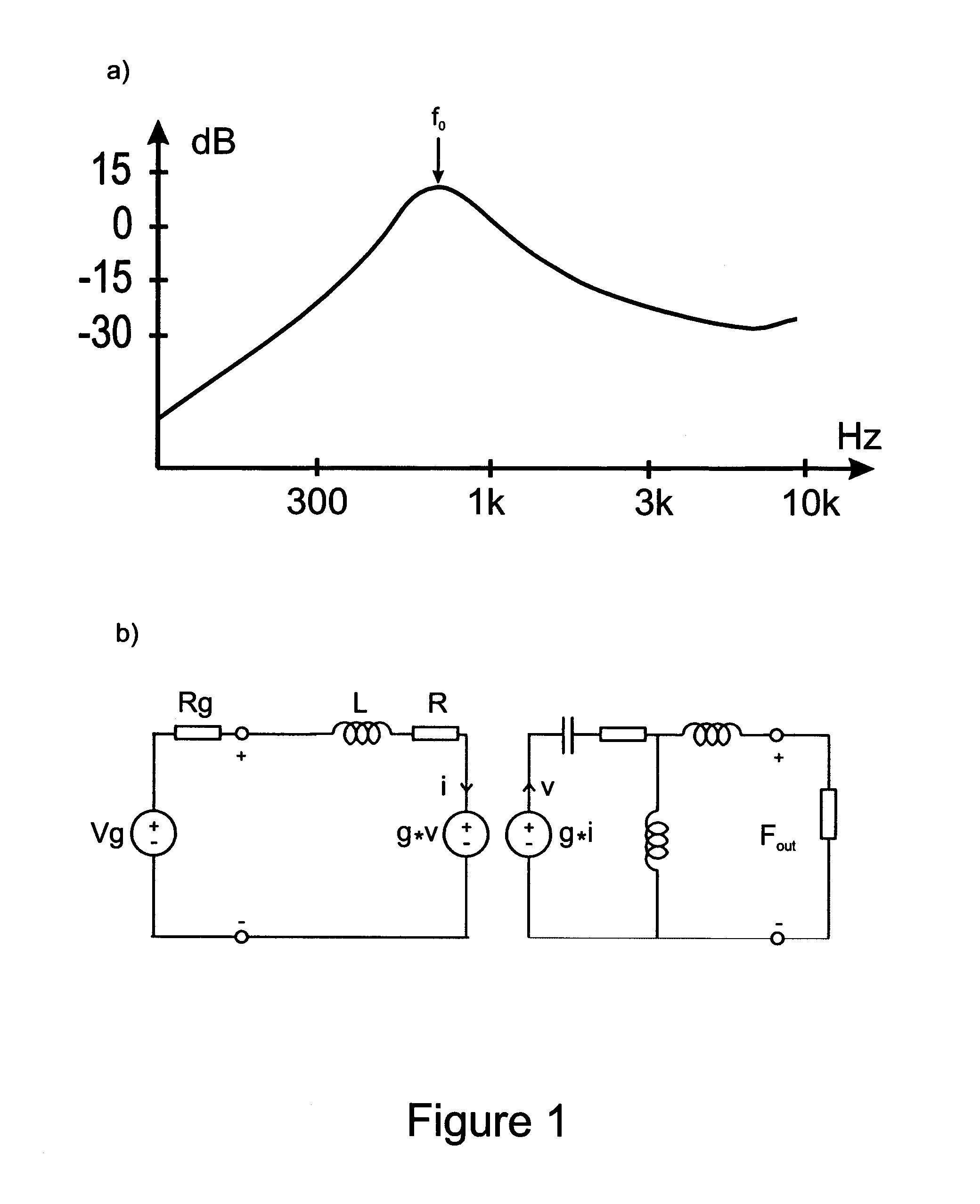
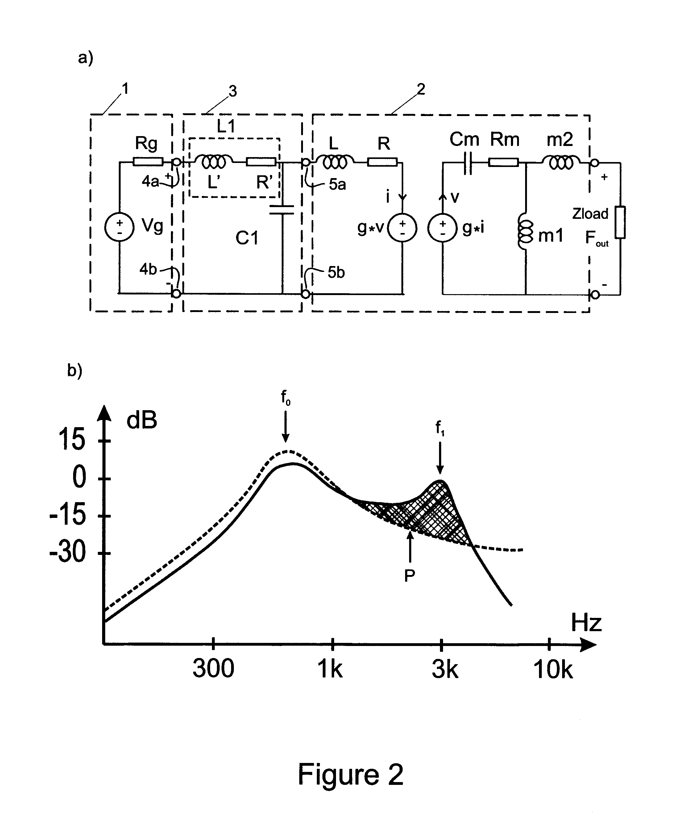
[0023]A preferred embodiment of the present invention is shown in FIG. 2. FIG. 2a, the hearing aid amplifier with output power amplifier 1 is represented by a Thévenin equivalent circuit, consisting of an ideal voltage source Vg and its output impedance Rg. The vibrator is modeled on a recognized but simplistic way (eg. by neglecting frequency-dependent losses) as an electro-mechanical analogy model 2 where the electric side of the vibrator consists of the inductance L of the coil and its ohmic losses R. The mechanical side of the vibrator consists suspension spring compliance Cm and its damping Rm while the counter weight mass m1 and the driving mass m2 couples the signal power to the mechanical load Zload. The mechanical resonance f0 formed by appropriate choice of Cm and m1 is given approximately by f0≅1 / sqrt[2π(m1*Cm)] where sqrt[ ] represents the square root operator. In this preferred embodiment an electrical network 3, comprising an inductor L1 in series with a first capacito...


PUM


Abstract

An electrical network for driving electromagnetic bone conduction vibrator / transducer of variable reluctance type which is applied between the vibrator terminals and the power amplifier terminals so that the vibrator mechanical output is maximized in the mid and high frequencies.

Description

TECHNICAL FIELD[0001]The present invention relates to a new device to connect an electromagnetic vibrator of variable reluctance type to an amplifier output stage in order to increase the maximum force output in bone conduction applications.STATE OF ART[0002]Hearing aids of bone conduction type has been known for a long time and uses the principle that a vibrator / speaker is applied to the skin behind the ear with a constant pressure. The vibrator is driven by an amplifier and the signal originates from a microphone or in some applications from an audiometer or other signal generators. In the 1980, the bone-anchored hearing aid was introduced where the vibrator is connected to a skin penetrating and bone-anchored titanium implants, see eg U.S. Pat. No. 4,498,461. Bone conduction devices are also used in communications equipment where you want the ear canal to be free and in audiometric equipment for testing hearing thresholds and speech recognition scores.[0003]In bone conduction app...

Claims


Application Information

Patent Timeline
Patent Type & Authority Patents(United States)
IPC IPC(8): H03G5/00H04R25/00H04R3/08H03G5/02H04R11/00H03G5/24H03H7/38
CPCH04R25/00H04R3/08H03G5/00H03G5/025H03G5/24H03H7/38H04R11/00H04R25/606H04R2460/13
Inventor HAKANSSON, BO
Owner OSSEOFON AB
Why Eureka
Try Eureka