Closed circuit forced hot air intraoperative patient warmer with improved sterility

a closed circuit, intraoperative technology, applied in the field of thermal blankets, can solve the problems of puddles of leaked water around the patient and on the operating room floor, patient may find the blankets highly uncomfortable, and the weight of the water filled blanket is high, so as to prevent the microbial contamination of the apparatus, improve the sterility, and discourage the infection of the patien

Active Publication Date: 2016-11-29
LEWIS RANDALL J
View PDF16 Cites 12 Cited by
  • Summary
  • Abstract
  • Description
  • Claims
  • Application Information

AI Technical Summary

Benefits of technology

[0029]whereby said system for said closed circuit forced hot air warmer of patient beds and blankets with improved sterility is cleaned internally by a vaporized disinfectant, preventing the microbial contamination of the apparatus, as recommended by the FDA, and thereby discouraging operative patient infections when the heater is employed during surgery.

Problems solved by technology

If the fluid-tilled device leaks or ruptures, the heated water disadvantageously creates puddles of leaked water around the patient and on the operating room floor.
Water filled blankets are heavy and the patient may find these blankets highly uncomfortable.
Release of the warm air can cause currents of unsterile air, containing bacteria, to surround the patient or the operative site, increasing prospects for infections.
Heating of the blanket is not achieved by the passage of warm air in a closed circuit.
This discharge of cooled / warmed air stirs microbes and floor dust in the room, creating the possibility of infecting the patient and workers in the operating room.
The device disclosed by the Feher patent does not use circulation of warm air in a closed system to warm the bed of a patient.

Method used


Image

  • Closed circuit forced hot air intraoperative patient warmer with improved sterility
  • Closed circuit forced hot air intraoperative patient warmer with improved sterility
  • Closed circuit forced hot air intraoperative patient warmer with improved sterility

Examples


Embodiment Construction

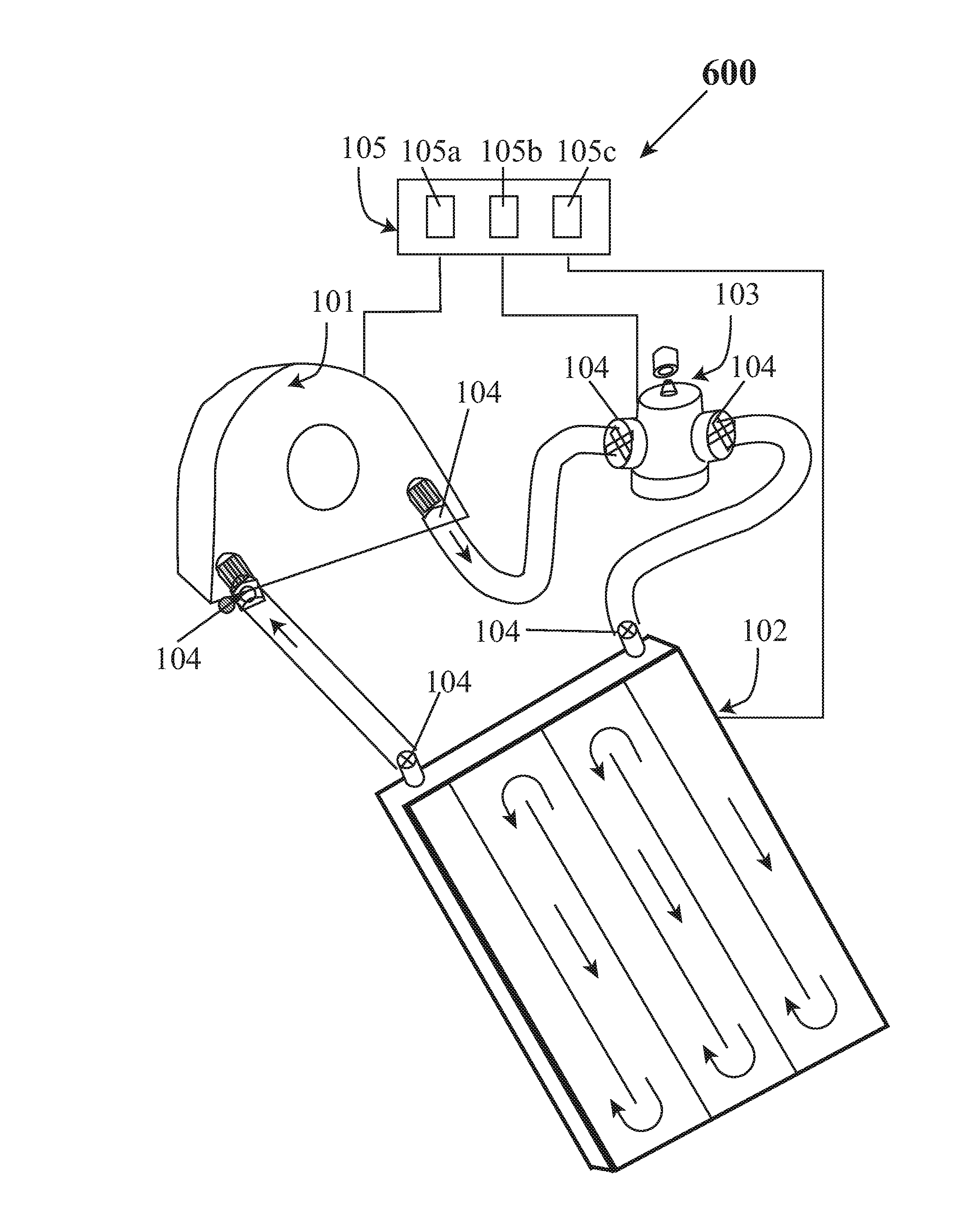
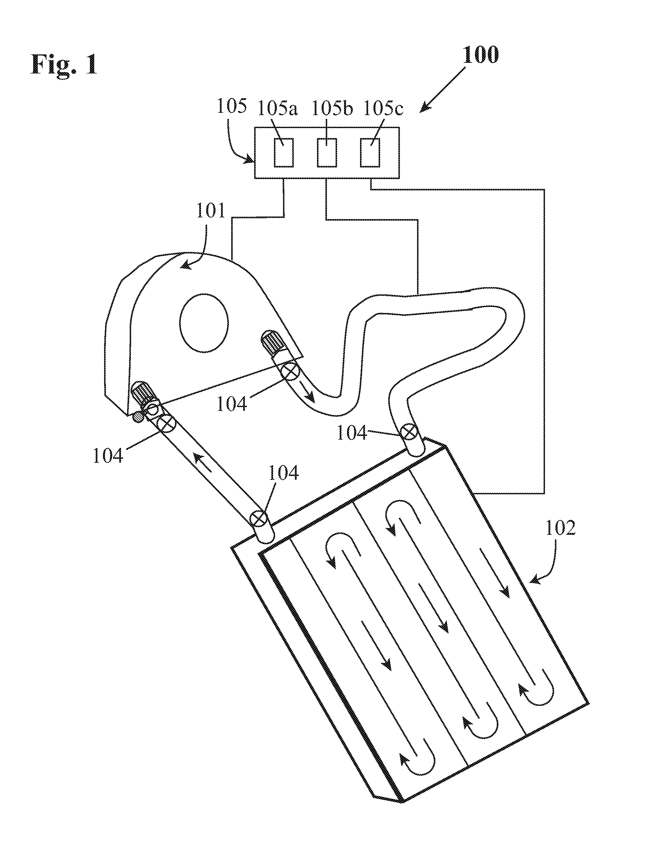
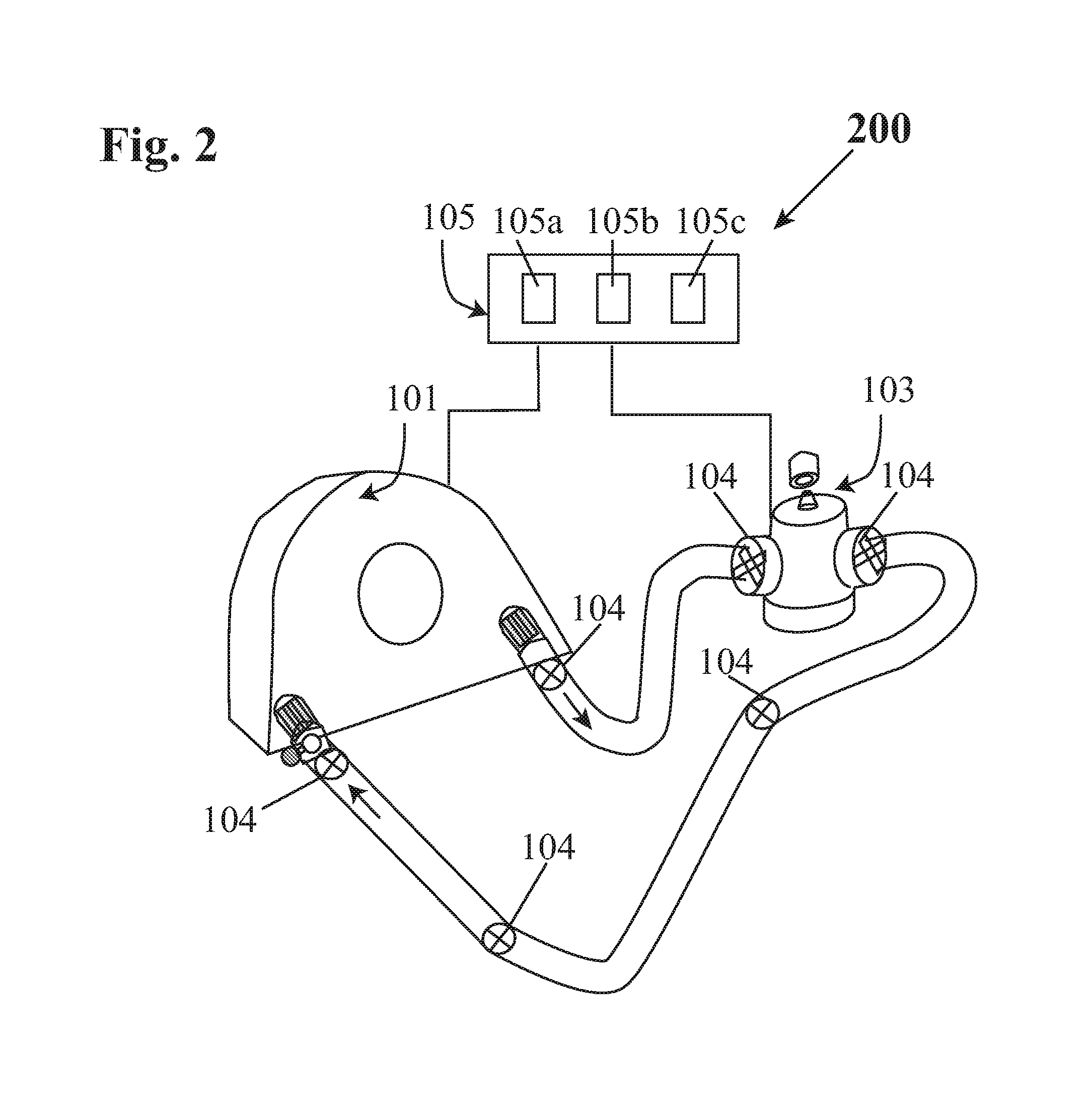
[0037]The objective of the invention is to provide warmth to a patient by a warmer that circulates heated air within a patient bed or blanket in a closed system without releasing warmed air into the area surrounding the patient or in the operating room, thereby preventing the possibility of patients suffering infections and hospital workers in the operating room being exposed to infecting microbes.

[0038]Measurements have shown that a patient on a hospital bed loses about 1.6 degrees C. body temperature during the first hour. Such body temperature loss can lead to hypothermia, shivering and may compromise the patient's healing ability, [See http: / / solutions.3m.com / wps / portal / 3M / en_EU / Healthcare-Europe / EU -Home / Products / InfectionPrevention / Patient_Warming / .] Patient warming beds and warming blankets are essential to prevent this onset of patient hypothermia.

[0039]For the past two decades, maintenance of patient body temperature during surgery has largely been achieved with forced hot ...


PUM

PropertyMeasurementUnit
pore sizeaaaaaaaaaa
flexibleaaaaaaaaaa
areaaaaaaaaaaa

Abstract

A system for a closed circuit forced hot air warmer of patient beds and blankets with improved sterility has a patient mattress or blanket microprocessor controlled warmer that circulates heated air in a closed system without releasing warmed air into the area surrounding the patient or into the operating room. The system helps to avoid the exposure of patients and hospital workers in the operating room to possible infecting microbes carried in unsterile turbulent air currents related to the release of air from non-closed systems. The machinery and flexible hoses of the system are initially sterilized by a microprocessor controlled antimicrobial mist generator. The system does not discharge jets of warmed air due to the closed circuit arrangement. Turbulent air flow previously produced in the vicinity of the patient by high velocity air jets is eliminated. An ambient, quiescent condition accorded by closed circuit heating prevents infection of patients and operating room personnel by microbe migration.

Description

FIELD OF THE INVENTION[0001]The present invention relates to thermal blankets; and, more particularly, to a system employing forced heated air in a closed circuit within a thermal blanket or mattress, warming the patient and preventing hypothermia, while maintaining the sterility of the operative area on the patient.DESCRIPTION OF THE PRIOR ART[0002]Numerous prior art patents and disclosures relate to warming of a patient mattress or blanket by the passage of warmed fluids. Warmed fluids may be heated water or heated air. If the fluid-tilled device leaks or ruptures, the heated water disadvantageously creates puddles of leaked water around the patient and on the operating room floor. Water filled blankets are heavy and the patient may find these blankets highly uncomfortable. Mattresses and blankets that circulate warm air discharge the air through a plurality of exit passages in the form of high velocity jets. The discharge creates turbulent circulation currents in the room air tha...

Claims


Application Information

Patent Timeline
Patent Type & Authority Patents(United States)
IPC IPC(8): A47C21/00A61F7/00
CPCA61F7/0097A61F2007/0055A61L2/22A61L2/26A61L9/16B01D46/00A61L2202/15A61L2209/14A61L2/00A61F7/0085A61F2007/0094
Inventor LEWIS, RANDALL J.
Owner LEWIS RANDALL J
Why Eureka
Try Eureka