Polishing composition
a technology of composition and polishing rate, applied in the direction of electrical equipment, chemistry apparatus and processes, other chemical processes, etc., can solve the problems of excessive polishing of the wiring portion, excessive polishing of the vicinity excessive polishing of the boundary surface, etc., to suppress the surface defect, the effect of reducing the step d
Active Publication Date: 2016-11-29
FUJIMI INCORPORATED
View PDF12 Cites 8 Cited by
- Summary
- Abstract
- Description
- Claims
- Application Information
AI Technical Summary
Benefits of technology
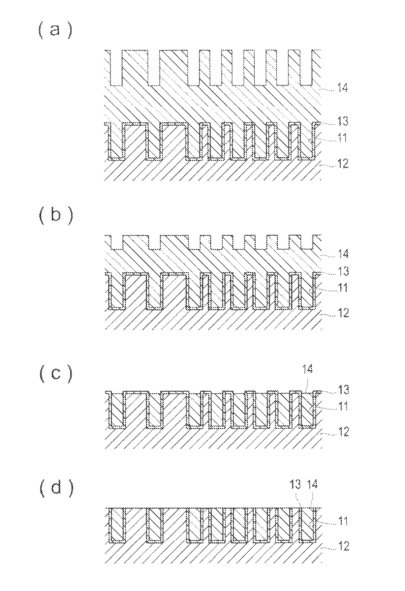
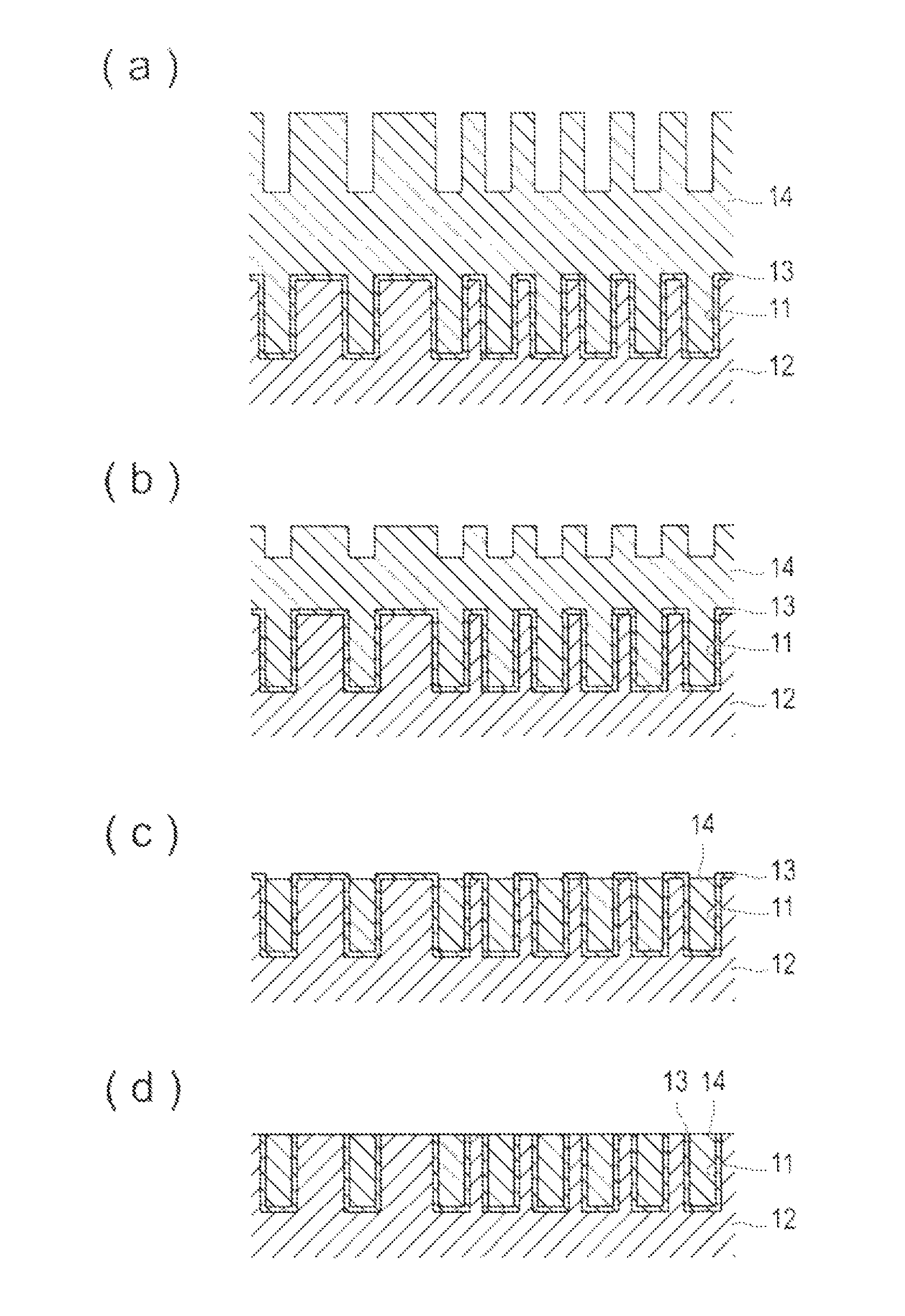
This patent is about a new polishing composition that can remove barrier layer and insulating film from semiconductor devices without causing surface defects like fang or erosion. Another goal is to reduce step defects like dishing while maintaining a high polishing rate for metal wiring layers.
Problems solved by technology
However, there is a problem that the so-called dishing that the wiring portion is excessively polished or a surface defect such as erosion and fang is caused by the metal film CMP.
As one factor to cause fang, it is considered that the components contained in the polishing liquid is unevenly localized at the boundary surface between the wiring layer and the region other than the wiring layer such as the carrier layer or the interlayer insulating film and thus the vicinity of the boundary surface is excessively polished.
For example, it is considered that the polishing rate locally increases at the boundary surface when the abrasive grain component contained in the polishing liquid is present at a high concentration in the vicinity of the boundary surface and thus the boundary surface is excessively polished.
Method used
View moreImage
Smart ImageViewing Examples
Examples
examples
[0084]The invention will be described in more detail with reference to the following examples and Comparative Examples. However, the technical scope of the invention is not limited to only the following Examples.
Login to View More PUM
| Property | Measurement | Unit |
|---|---|---|
| aspect ratio | aaaaa | aaaaa |
| aspect ratio | aaaaa | aaaaa |
| particle size | aaaaa | aaaaa |
Abstract
[Problem] Provided is a polishing composition that can sufficiently maintain a high polishing rate for a barrier layer and an insulating film and suppress the occurrence of a surface defect such as erosion or fang.[Solution] Provided is a polishing composition which is used in the application to polish a polishing object having a barrier layer, a metal wiring layer and an insulating film, the polishing composition including abrasive grains, an oxidant, a metal corrosion inhibitor, a pH adjusting agent and water, in which an aspect ratio of abrasive grains is 1.22 or less and a ratio D90 / D10 of a diameter D90 of particles when a cumulative particle weight from the fine particle side reaches 90% of the total particle weight to a diameter D10 of particles when the cumulative particle weight from the fine particle side reaches 10% of the total particle weight of the entire particles is 1.5 or more in a particle size distribution of the abrasive grains determined by a laser diffraction scattering method.
Description
TECHNICAL FIELD[0001]The present invention relates to a polishing composition.BACKGROUND[0002]In recent years, new fine processing techniques have been developed as the LSI is highly integrated and exhibits high performance. The chemical mechanical polishing (hereinafter, simply referred to as CMP as well) method is also one of them and is a technique that is frequently used for the flattening of the interlayer insulating film, the formation of metal plug and the formation of embedded wiring (damascene wiring) in the LSI manufacturing process, especially the multilayer wiring forming process.[0003]A general method of CMP is a method in which the polishing pad is pasted onto a circular polishing table (platen), and the polishing pad surface is wet with a polishing agent, the surface on which a metal film is formed of the substrate is pressed against the polishing pad, the polishing table is rotated in a state in which a predetermined pressure (hereinafter, simply referred to as the p...
Claims
Login to View More Application Information
Patent Timeline
 Patent Type & Authority Patents(United States)
IPC IPC(8): C09K13/00H01L21/321C09K3/14C09G1/02H01L21/3105
CPCC09G1/02C09K3/1436C09K3/1463H01L21/3212H01L21/31053
Inventor UMEDA, TAKAHIROONISHI, SHOGOYOSHIKAWA, TAKESHIKACHI, YOSHIHIRO
Owner FUJIMI INCORPORATED
Features
- R&D
- Intellectual Property
- Life Sciences
- Materials
- Tech Scout
- Unparalleled Data Quality
- Higher Quality Content
- 60% Fewer Hallucinations
Learn More Browse by: Latest US Patents, China's latest patents, Technical Efficacy Thesaurus, Application Domain, Technology Topic, Popular Technical Reports.
© 2025 PatSnap. All rights reserved.Legal|Privacy policy|Modern Slavery Act Transparency Statement|Sitemap|About US| Contact US: help@patsnap.com


