Audio amplifier using multi-level pulse width modulation
a multi-level pulse width modulation and audio amplifier technology, applied in the direction of low-frequency amplifiers, electrical transducers, transducer casings/cabinets/supports, etc., can solve the problems of poor power efficiency at such small audio input signals, poor low-frequency power efficiency, and low-frequency power consumption, so as to reduce the breakdown voltage requirements of semiconductor switches, the effect of robustness and low-cos
- Summary
- Abstract
- Description
- Claims
- Application Information
AI Technical Summary
Benefits of technology
Problems solved by technology
Method used
Image
Examples
first embodiment
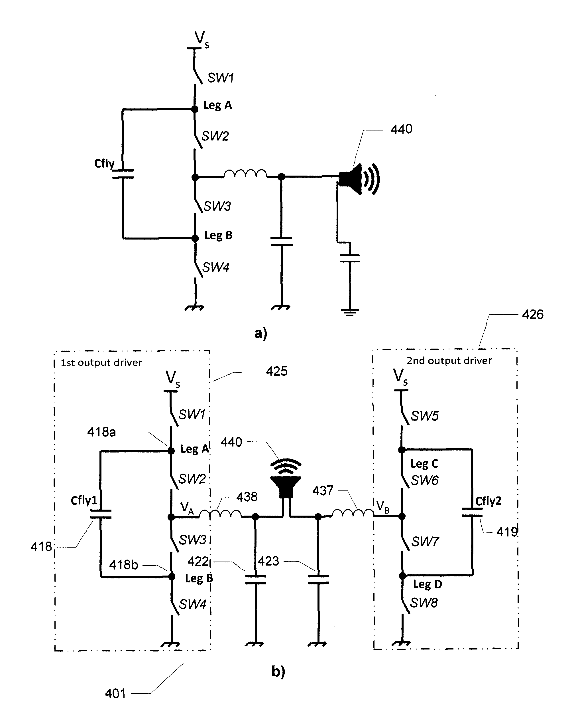
[0113]In the invention, the various pulse width modulated control signals are configured such that the first and fifth fourth pulse width modulated control signals are in opposite phase at zero modulation. The same applies for the second and 6th pulse width modulated control signals, the third and 7th pulse width modulated control signals and the fourth and 8th pulse width modulated control signals. This configuration of the pulse width modulated control signals ensures, in combination with the respective settings of the predetermined DC voltages of the flying capacitors Cfly1, Cfly2 (418, 419) to about one-half of the first DC supply voltage VS, that a 3-level pulse width modulated output signal is generated between the first and second output nodes VA and VB and therefore applied as a load signal to the loudspeaker load 440. This 3-level pulse width modulated output signal is illustrated on FIG. 5 as waveform 507. As illustrated the present 3-level pulse width modulated output sig...
second embodiment
[0114]In the invention, the various pulse width modulated control signals are configured such that the first and fifth fourth pulse width modulated control signals are inverted and additionally phase shifted with + / −90 degrees relative to each other. The same applies for a corresponding phase relationship between the second and 6th pulse width modulated control signals, the third and 7th pulse width modulated control signals and the fourth and 8th pulse width modulated control signals. This adaptation of the pulse width modulated control signals ensures, in combination with the setting of both of the predetermined DC voltages of the flying capacitors Cfly1, Cfly2 (418, 419) to about one-half of the first DC supply voltage VS, that a 5-level pulse width modulated output signal is generated between the first and second output nodes VA and VB and therefore applied as a load signal to the loudspeaker load 440. This 5-level pulse width modulated output signal is illustrated on FIG. 5 as ...
third embodiment
[0115]FIG. 6 illustrates a CMOS based single-ended multi-level output driver 601 coupled to a loudspeaker load 640 through a lowpass filter comprising load inductor 637 and load capacitor 635 in accordance with the invention. The single-ended multi-level output driver 601 comprises, in addition to semiconductor switches SW1, SW2, SW3, SW4 of the single-ended output driver depicted on FIG. 4a), a 5th CMOS semiconductor switch SW5 and a sixth semiconductor switch SW6 to bring the total number of series coupled or connected CMOS semiconductor switches up to six. The 5th CMOS semiconductor switch SW5 is coupled in series with the upper or first DC supply voltage VS and in series to the first and second semiconductor switches SW1 and SW2 which are coupled to an output node VA. The 6th CMOS semiconductor switch SW6 is coupled in series between GND and series coupled third and fourth semiconductor switches SW3 and SW4 which are coupled to the output node VA. Consequently, both an upper leg...
PUM
 Abstract
Description
Claims
Application Information
 - R&D
- Intellectual Property
- Life Sciences
- Materials
- Tech Scout
- Unparalleled Data Quality
- Higher Quality Content
- 60% Fewer Hallucinations
Browse by: Latest US Patents, China's latest patents, Technical Efficacy Thesaurus, Application Domain, Technology Topic, Popular Technical Reports.
© 2025 PatSnap. All rights reserved.Legal|Privacy policy|Modern Slavery Act Transparency Statement|Sitemap|About US| Contact US: help@patsnap.com


