Roofing, cladding or siding product, its manufacture and its use as part of a solar energy recovery system

a technology for solar energy recovery and roofing, applied in the direction of roof covering ventilation, photovoltaics, solar heat collectors for particular environments, etc., can solve the problems of difficult mass production, poor durability and environmental resistance, and difficult installation, so as to reduce the cost of mass production, the effect of easy installation

Active Publication Date: 2016-12-13
ZINNIATEK
View PDF43 Cites 22 Cited by
  • Summary
  • Abstract
  • Description
  • Claims
  • Application Information

AI Technical Summary

Benefits of technology

[0012]In various aspects, the present invention provides a roofing, cladding or siding product which is light weight, easy to install, weatherproof, durable, resistant to environmental wear, and aesthetically pleasing. One embodiment relates to a module that can be used to form a weatherproof covering over top of a building surface. Another embodiment is a module which can, in additional to forming a weatherproof covering, be used as part of a thermal energy recovery or removal system. Yet another embodiment is a module which can, in addition to forming a weatherproof covering, and optionally in addition to being useful as part of a thermal energy recovery or removal system, bears an array of solar cells to generate electrical energy.
[0019]In one embodiment, the profile of the underside of the underlapping surface is patterned in a manner to (1) create turbulence in the airflow, (2) increase the surface area of the module in contact with the passing airflow compared to a module lacking such a surface pattern, or both (1) and (2). In one embodiment, the profile of the underside of the underlapping region comprises a plurality of projections that create a tortuous pathway above the actual or notional plane of the building surface. In one embodiment, the profile of the underside of the underlapping region comprises corrugated form of alternating parallel grooves and ridges.
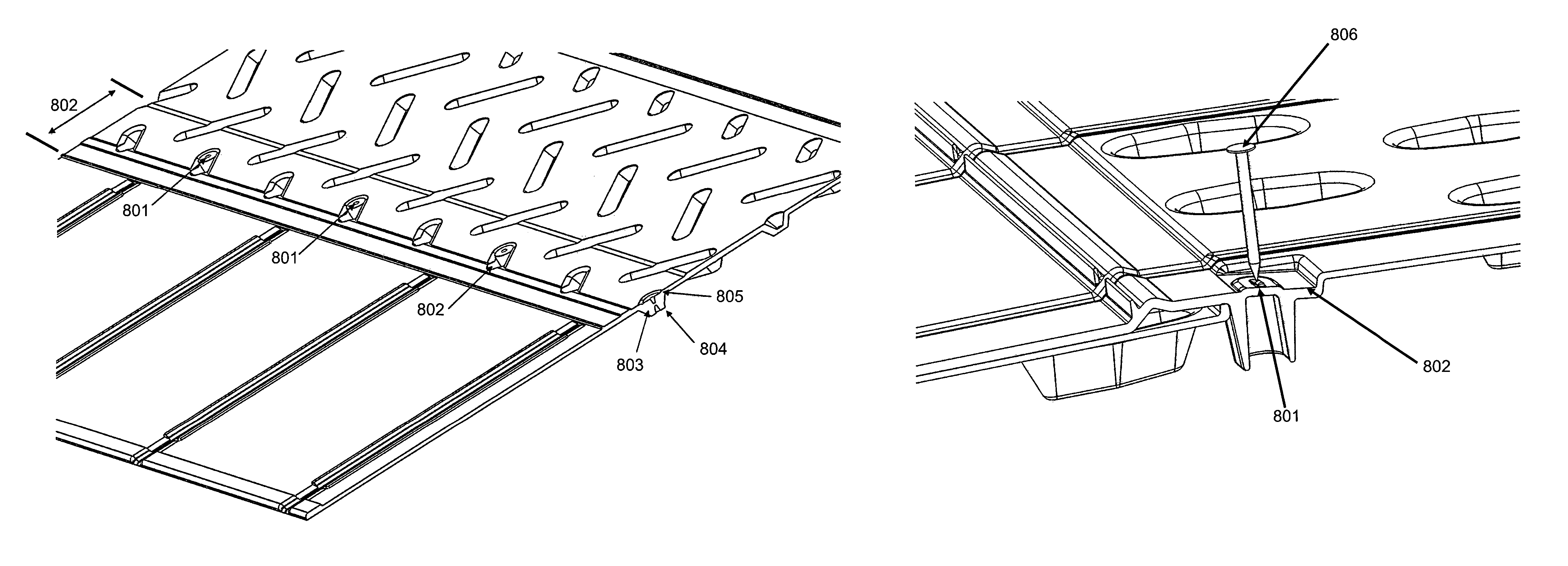
[0024]In one embodiment, the top and bottom sides of the underlapping region contain complementary locating elements. In one embodiment, the underlapping region is profiled to define one or more regions for fixing by a penetrative fastener. In one embodiment, the one or more regions for fixing by a penetrative fastener are adapted to receive a nail or screw gun head to accurately locate the fixing.
[0049]In a further aspect, the invention provides a roofing, cladding or siding component suitable or installed to pass solar energy received by at least some of its regions into an underlying airstream, and with a photovoltaic regional functionality with a photovoltaic receiving region to convert received solar energy into an electrical output. In one embodiment, when as part or as part of a series down or across an underlying building surface, is useable whereby each photovoltaic receiving region is fully exposed despite partial overlapping of one component to another to better shed water; and is useable whereby, despite attachment to the underlying building surface, there is a setout from the underlying building surface sufficient to allow a passage of an underlying airstream.

Problems solved by technology

The disadvantages of traditional products for these purposes are that they are heavy and difficult to install, many do not have good durability and environmental resistance, and many are difficult to mass produce economically.
This can increase the expense of air conditioning and environmental control.
Generally, the collection of any significant amount of solar energy requires a large area of photovoltaic surface be exposed to unobscured sunlight.
However, PV roofing and cladding products can be complex and costly to produce, especially in 3D polymer form and in large scale production.
They can also lack durability, aesthetics and weather resistance that would otherwise be desirable in a roofing product.
In terms of durability, many conventional PV roofing and cladding products are inherently unstable when exposed to sunlight for an extended period of time.
Moreover, prior art photovoltaic roofing shingles are generally difficult to install.
Such junctions can be time consuming to connect and are often a failure point of the product because they corrode or the connections are incorrectly made.
A further difficulty is that some of the energy from the solar cells will simply be dissipated as heat.
The hotter the cells get, the less efficiently they work, and the higher the heat transmission through the roof surface into the building.

Method used


Image

  • Roofing, cladding or siding product, its manufacture and its use as part of a solar energy recovery system
  • Roofing, cladding or siding product, its manufacture and its use as part of a solar energy recovery system
  • Roofing, cladding or siding product, its manufacture and its use as part of a solar energy recovery system

Examples


Embodiment Construction

[0099]It is to be appreciated that certain aspects, modes, embodiments, variations and features of the invention are described below in various levels of detail in order to provide a substantial understanding of the present technology.

[0100]The present technology is described herein using several definitions, as set forth throughout the specification. Unless otherwise stated, the singular forms “a,”“an,” and “the” include the plural reference. For example, a reference to “a device” includes a plurality of devices.

[0101]As used herein the term “and / or” means “and” or “or”, or both.

[0102]As used herein “(s)” following a noun means the plural and / or singular forms of the noun.

[0103]Relative terms, such as “lower” or “bottom”, “upper” or “top,” and “front” or “back” may be used herein to describe one element's relationship to another element as illustrated in the Figures. It will be understood that relative terms are intended to encompass different orientations of the device in addition...


PUM

PropertyMeasurementUnit
lengthaaaaaaaaaa
lengthaaaaaaaaaa
thicknessaaaaaaaaaa

Abstract

This disclosure provides a roofing, cladding or siding product which is light weight, easy to install, durable and resistant to environmental wear. One embodiment relates to a module that can be used to form a weatherproof covering over top of a building surface. Another embodiment is a module which can, in additional to forming a weatherproof covering, be used as part of a thermal energy recovery or removal system. Yet another embodiment is a module which can, in addition to forming a weatherproof covering, and optionally in addition to being useful as part of a thermal energy recovery system, bears an array of solar cells to generate electrical energy. Assemblies, systems, uses, and methods of manufacture are also described.

Description

CROSS-REFERENCE TO RELATED APPLICATIONS[0001]This application claims the benefit of priority to international patent application number PCT / NZ2012 / 000221, having a filing date of Nov. 30, 2012, which claims the benefit of priority to New Zealand patent application number NZ 596793, having a filing date of Nov. 30, 2011, the complete disclosures of which are hereby incorporated by reference for all purposes.TECHNICAL FIELD[0002]The present technology relates generally to the manufacture of roofing, cladding and / or siding products, and to systems, assemblies, methods and uses for such a product, including the collection of solar and / or thermal energy.BACKGROUND[0003]The following description is provided to assist the understanding of the reader. None of the information provided or references cited is admitted to be prior art to the present invention.[0004]Environmental and sustainability concerns have created a need for alternative or renewable energy systems. Solar energy is one type...

Claims


Application Information

Patent Timeline
Patent Type & Authority Patents(United States)
IPC IPC(8): E04D13/17E04D13/00E04D1/30F28F3/04H02S20/23F24J2/52F24J2/46H02S40/12H02S40/44H02S20/25F24J2/04F24J2/00
CPCE04D13/17E04D1/30E04D13/00F24J2/4614F24J2/5228F24J2/5245F28F3/048H02S20/23H02S20/25H02S40/12H02S40/44E04D2001/309F24J2/045F24J2002/0061Y02B10/12Y02B10/20Y02B10/70Y02E10/47Y02E10/60Y10T29/49623E04D1/2918F24S20/67F24S25/40F24S25/61F24S40/44F24S2020/13Y02B10/10Y02E10/50
Inventor HAYNES, ANDREW LEOPARTRIDGE, ASHTON CYRILMCKEE, JOHN WASONMORROW, CHRISTOPHER CHARLESBUCKINGHAM, SAMUEL GWYNNKVASNICKA, JOHAN MIROSGIURGIU, GABRIEL IOAN
Owner ZINNIATEK
Why Eureka
Try Eureka