Beam-splitting integrated optical element and optical transmitter module

a beam-splitting integrated and optical element technology, applied in the field of beam-splitting integrated optical elements and optical transmitter modules, can solve the problems of reducing the yield rate of the optical transmitter module b, optical power loss, etc., to facilitate the reduction of alignment difficulty and alignment time of the optical transmitter module, and prevent scattering

Active Publication Date: 2016-12-27
ELITE ADVANCED LASER CORP
View PDF5 Cites 3 Cited by
  • Summary
  • Abstract
  • Description
  • Claims
  • Application Information

AI Technical Summary

Benefits of technology

[0008]The invention is directed to a beam-splitting integrated optical element capable of preventing the scattering due to beam-splitting at the vertex in order to lower the optical power loss and the beam-splitting ratio offset and facilitate in reduction of the alignment difficulty and the alignment time for the optical transmitter module.

Problems solved by technology

Since the vertex X formed by connecting the total internal reflection surfaces TIR1 and TIR2 together are prone to have curvature due to manufacturing process factors, the beam B is prone to be scattered at the vertex X, resulting in an optical power loss and a beam-splitting ratio offset thereby lowering a yield rate of the optical transmitter module 10.
Accordingly, how to solve the aforementioned problems has become one of important issues in the related art.

Method used


Image

  • Beam-splitting integrated optical element and optical transmitter module
  • Beam-splitting integrated optical element and optical transmitter module
  • Beam-splitting integrated optical element and optical transmitter module

Examples


first embodiment

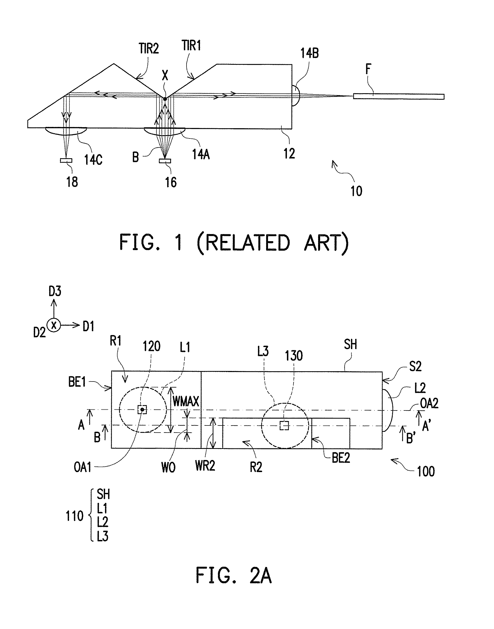
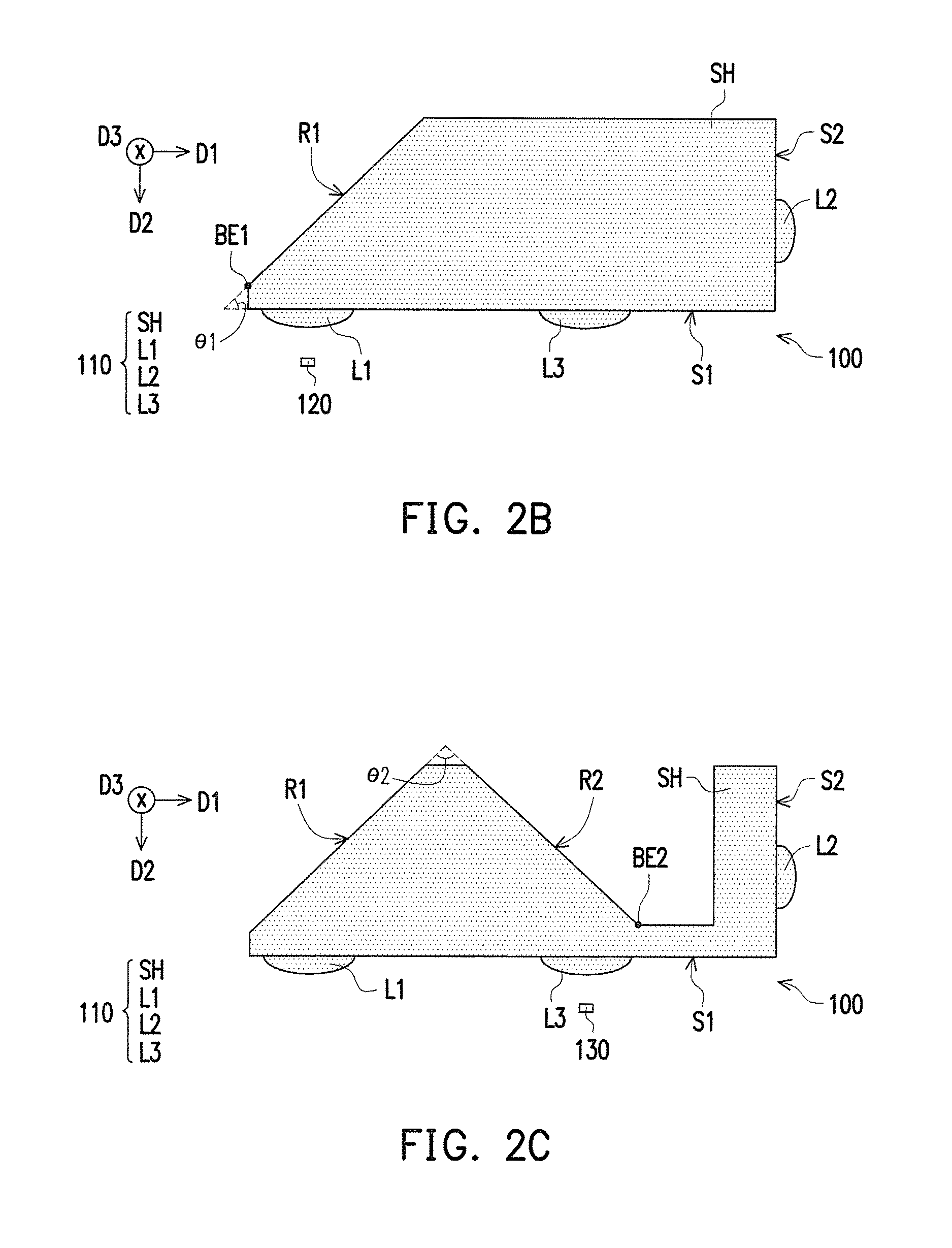
[0041]FIG. 2A is a schematic top view of an optical transmitter module according to the invention. FIG. 2B and FIG. 2C are respectively schematic cross-sectional views along section lines A-A′ and B-B′ in FIG. 2A. FIG. 2D and FIG. 2E are schematic diagrams of an optical path of the optical transmitter module in FIG. 2A. FIG. 2F and FIG. 2G are respectively schematic diagrams of optical fields OF1 and OF2 in FIG. 2D. FIG. 2H is a schematic diagram of an optical form OF3 in FIG. 2E.

[0042]Referring to FIG. 2A to FIG. 2H, an optical transmitter module 100 includes a beam-splitting integrated optical element 110, at least one first light source 120 and at least one optical detector 130. In this embodiment, the number of each of the first light source 120 and the optical detector 130 is one, but not limited thereto.

[0043]The beam-splitting integrated optical element 110 includes a shell SH, at least one first lens L1, and at least one second lens L2. In this embodiment, the number of each...

second embodiment

[0054]FIG. 3A is a schematic top view of an optical transmitter module according to the invention. FIG. 3B and FIG. 3C are respectively schematic cross-sectional views along section lines A-A′ and B-B′ in FIG. 3A. FIG. 3D and FIG. 3E are schematic diagrams of an optical path of the optical transmitter module in FIG. 3A. Referring to FIG. 3A to FIG. 3E, an optical transmitter module 200 is similar to the optical transmitter module 100, and the same elements are indicated by the same reference numbers, which are not repeated hereinafter.

[0055]A major difference between the optical transmitter module 200 and the optical transmitter module 100 is that, in a beam-splitting integrated optical element 210, a first reflective surface R1 and a second reflective surface R2 of a shell SHA are arranged in the third direction D3 perpendicular to the first optical axis OA1 and the second optical axis OA2. Further, the projection of the first lens L1 is overlapped with the first reflective surface...

third embodiment

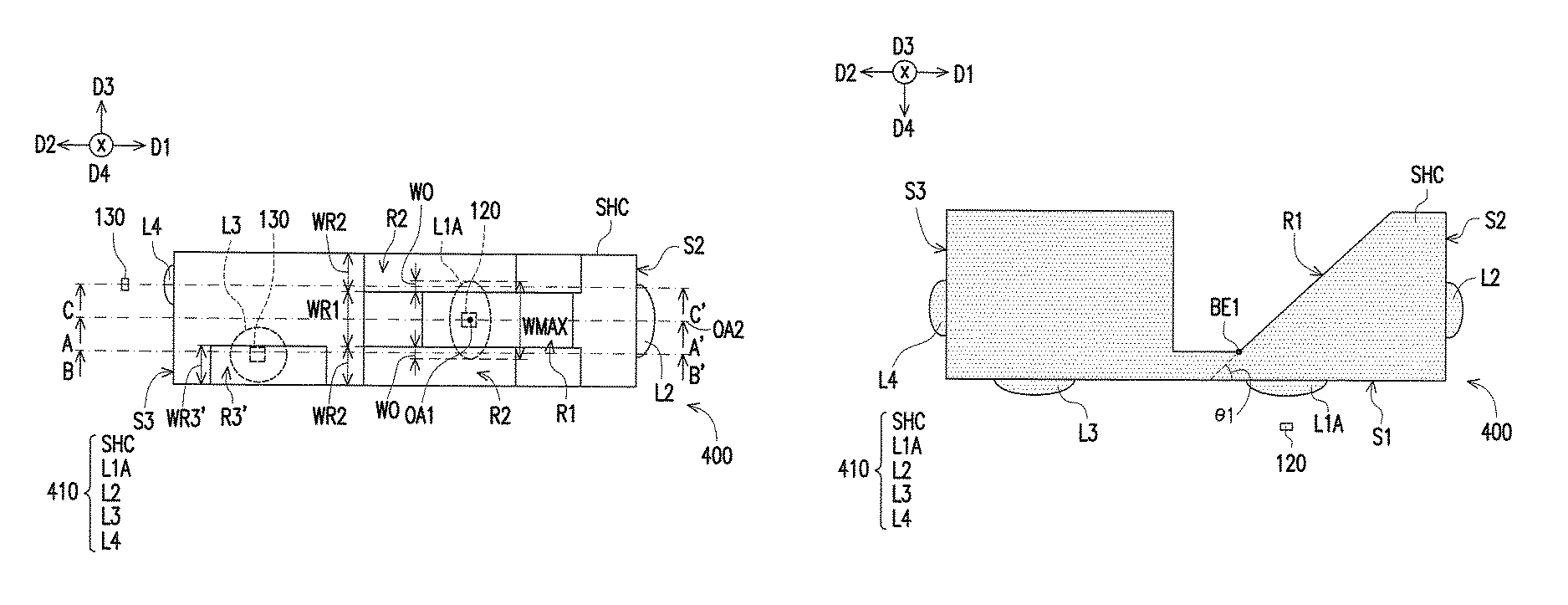
[0061]FIG. 4A is a schematic top view of an optical transmitter module according to the invention. FIG. 4B and FIG. 4C are respectively schematic cross-sectional views along section lines A-A′ and B-B′ in FIG. 4A. FIG. 4D and FIG. 4E are schematic diagrams of an optical path of the optical transmitter module in FIG. 4A. Referring to FIG. 4A to FIG. 4E, an optical transmitter module 300 is similar to the optical transmitter module 200, where the same elements are indicated by the same reference numbers, and thus the disposition relation and effectiveness related thereto are not repeated hereinafter.

[0062]A major difference between the optical transmitter module 300 and the optical transmitter module 200 is that, in a beam-splitting integrated optical element 310, a shell SHB has a plane S3 as replacement to the third reflective surface R3. The plane S3 is connected and perpendicular to the first lens surface S1, and the third lens L3 is disposed on the plane S3.

[0063]Referring to FIG...


PUM


Abstract

A beam-splitting integrated optical element including a shell, at least one first lens, and at least one second lens is provided. The shell includes a first lens surface, a second lens surface, at least one first reflective surface, and at least one second reflective surface. A bottom edge of each first reflective surface and a bottom edge of each second reflective surface are not connected to each other. The at least one first lens is disposed on the first lens surface. The at least one second lens is disposed on the second lens surface, and each second lens has a second optical axis. Each second reflective surface is located at at least one side of the corresponding second optical axis and located on a transmission path of only a portion of a first beam. An optical transmitter module incorporating said beam-splitting optical element is also provided.

Description

CROSS REFERENCE TO RELATED APPLICATION[0001]This application claims the priority benefit of Taiwan application serial no. 104143340, filed on Dec. 23, 2015. The entirety of the above-mentioned patent application is hereby incorporated by reference herein and made a part of specification.BACKGROUND OF THE INVENTION[0002]1. Field of the Invention[0003]The invention relates to a beam-splitting integrated optical element and an optical transmitter module.[0004]2. Description of Related Art[0005]With advancements in communication technologies, communication methods are no longer limited only to be implemented by using electrical signals. Recently, optical communication technologies have been developed to realize signal transmission with optical signals. Because transmission speed and distance of light is far higher and longer than electrons, optical communication technologies have gradually become the mainstream in the market. Based on high bandwidth requirements, demands for optical tra...

Claims


Application Information

Patent Timeline
Patent Type & Authority Patents(United States)
IPC IPC(8): G02B6/42G02B27/30G02B27/14
CPCG02B6/4214G02B27/14G02B27/30G02B6/4206G02B6/2817G02B6/4246G02B6/4286G02B27/108G02B27/145
Inventor CHENG, CHU-LIANGLIN, YI-TSENG
Owner ELITE ADVANCED LASER CORP
Why Eureka
Try Eureka