Device for manipulating charged particles via field with pseudopotential having one or more local maxima along length of channel

a charge particle and field technology, applied in the field of charge particle optics and mass spectrometry, can solve the problems of low efficiency of charge particle transportation along the length of the channel, loss of other charged particles outside the boundaries of the channel of mass filter, and loss of other charged particles outside the channel boundary

Active Publication Date: 2017-01-03
SHIMADZU RES LAB EURO
View PDF52 Cites 35 Cited by
  • Summary
  • Abstract
  • Description
  • Claims
  • Application Information

AI Technical Summary

Benefits of technology

[0037]An advantage of the present invention is the capability of combining positively and negatively charged particles in a single transported packet.
[0038]Where the present application refers to “charged particle(s)”, this includes a reference to ion(s), being a preferred charged particle with which the present application is concerned.
[0039]Where the present application refers to “with a certain interval of time”, this includes a reference to a desired or predetermined or preselected interval or period of time.
[0040]The power supply can also encompass the generation and / or provision of additional voltages to the electrodes as discussed herein.
[0041]As discussed herein in more detail, the present inventors have found that further advantages are achievable when the voltages supplied by the power supply are generated using a digital method. That is, the supply voltages have the form of a digital waveform. The advantages associated with digital drive / digital method approach and the implementation of such an approach are discussed in more detail below.
[0042]The present inventors have also found that significant advantages can be achieved if the supply voltages are one or more selected from high-frequency harmonic voltages, periodic non-harmonic high-frequency voltages, high-frequency voltages having a frequency spectrum which contains two or more frequencies, high-frequency voltages having frequency spectrum which contains an infinite set of frequencies, and high-frequency pulsed voltages, wherein the said voltages are suitably converted into time-synchronised trains of high-frequency voltages and / or a superposition of the said voltages is used. The use of these waveforms, singly or in combination, optionally with the methods of modulation disclosed herein, allow the device to be configured to the wide range of applications described herein by adjusting the shape of the created pseudopotential. The shape of the pseudopotential is important for the optimizing the device for application to which it is being applied or the mode of operation within a particular device. For example by adjusting the harmonics provided by the voltage supply the device can be configured to provide optimum performance for a particular application, for example one or more of achieving a maximum mass range of transmission, maximum amount charge transmitted, allowing ions to be resonantly excited within certain regions, collecting ions with high energy spread, separating ions according to mass or mobility, and fragmenting ions by low energy electrons. Thus, this feature permits a wider range of applications to be achieved in a more flexible, reliable and efficient manner compared with prior art devices.

Problems solved by technology

The other charged particles would lose the stability of their trajectories, and would be lost outside the boundaries of the channel of the mass filter.
One can see that in the case of an absence of additional electric fields in the vicinity of the axis of the device, the forces enabling the movement of charged particles along the axis of the transporting device would practically be absent due to symmetry of the electrodes and high frequency of the electric field (U.S. Pat. No. 5,818,055 and U.S. Pat. No. 6,894,286), and the transfer of charged particles along the length of the channel for transportation would not be very efficient.
However, since the positively charged particles are grouped in the vicinities of minima of the progressive wave of potential of the quasi-static electric field, and negatively charged particles are grouped in the vicinities of maxima of the progressive wave of potential of the quasi-static electric field, it would not be possible to ensure transportation of positively and negatively charged particles in an integrated packet of charged particles using this method.
If there are several different RF electric fields with essentially different frequencies, then individual pseudopotentials would be summed for these electric fields, however, if the difference between the frequencies of these RF fields is insignificant, this rule would not be valid.
The approach based on the use of pseudopotential would not give a correct solution, because under the conditions where a charged particle moves near the boundary of the zone of stability, and a resonance takes place between “slow” oscillations of the charged particle and the RF electric field, the displacement of the charged particle during one period of the RF electric field under no conditions could be considered to be small.
However, the device of U.S. Pat. No. 6,812,453 does not provide a capability of combining positively and negatively charged particles in a single transported packet.

Method used


Image

  • Device for manipulating charged particles via field with pseudopotential having one or more local maxima along length of channel
  • Device for manipulating charged particles via field with pseudopotential having one or more local maxima along length of channel
  • Device for manipulating charged particles via field with pseudopotential having one or more local maxima along length of channel

Examples


example 1

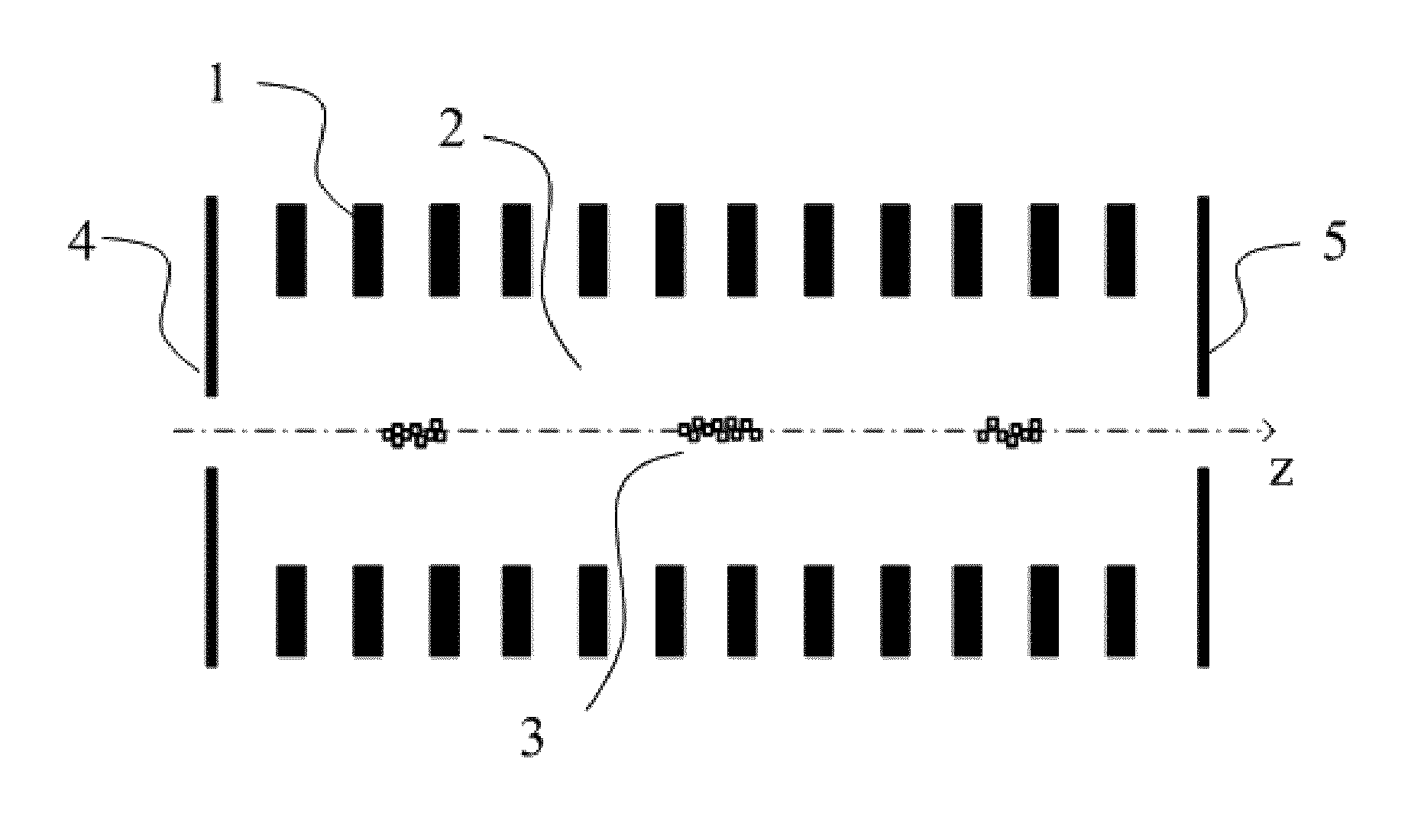
[0449]For the electrodes 1, the system of electrodes described above was used, the system consisting of periodic sequence of plane diaphragms with square cross-section (FIG. 53). Geometrical parameters and dimensions of the specified system of electrodes are shown in FIG. 69, geometrical dimensions of single diaphragm with square aperture are shown in FIG. 70.

[0450]For the supply voltage, sinusoidal supply with amplitude modulation was used. Periodic sequence of electrodes was subdivided into groups of four electrodes. The first electrodes in each group were supplied with electric voltage +U0 cos(δt)cos(ωt), the second electrodes were supplied with voltage +U0 sin(δt)cos(ωt), the third electrodes were supplied with voltage −U0 cos(δt)cos(ωt), the fourth electrodes were supplied with voltage −U0 sin(δt)cos(ωt). The fundamental frequency of sinusoidal supply was selected to be equal to ω=1 MHz, the frequency of amplitude modulation of sinusoidal supply was selected to be equal to δ=1 ...

example 2

[0451]For the electrodes 1, the system of electrodes described above was used, the system consisting of periodic sequence of alternating plane diaphragms with rectangular cross-sections (FIG. 59). Geometrical parameters and dimensions of the specified system of electrodes are shown in FIG. 72, geometrical dimensions of single diaphragm with square aperture are shown in FIG. 73.

[0452]For the supply voltage, sinusoidal supply with amplitude modulation was used. Periodic sequence of electrodes was subdivided into groups of four electrodes. The first electrodes in each group were supplied with electric voltage +U0 cos(δt)cos(ωt), the second electrodes were supplied with voltage +U0 sin(δt) cos(ωt), the third electrodes were supplied with voltage −U0 cos(δt)cos(ωt), the fourth electrodes were supplied with voltage −U0 sin(δt) cos(ωt). The fundamental frequency of sinusoidal supply was selected to be equal to ω=1 MHz, the frequency of amplitude modulation of sinusoidal supply was selected...

example 3

[0453]For the electrodes 1, the system of electrodes described above was used, the system consisting of periodic sequence of plane diaphragms, consisting of plane electrodes and providing quadrupole structure of electric field in the section of diaphragm (FIG. 55). Geometrical parameters and dimensions of the specified system of electrodes are shown in FIG. 75, geometrical dimensions of single square diaphragm consisting of four independent plane electrodes are shown in FIG. 76.

[0454]For the supply voltage, sinusoidal supply with amplitude modulation was used. The electrodes, designated in FIG. 76 as > electrodes, electric voltage was supplied opposite in phase with electric voltage supplied to the electrodes designated in FIG. 76 as > electrodes. Periodic sequence of diaphragms was subdivided into groups of four, composed of consecutive diaphragms. The first diaphragms in each group of four were supplied with electric voltage ±U0 cos(δt)cos(ωt) (the sign of > or > is selected depen...


PUM


Abstract

The present invention is concerned with a device for charged particle transportation and manipulation. Embodiments provide a capability of combining positively and negatively charged particles in a single transported packet. Embodiments contain an aggregate of electrodes arranged to form a channel for transportation of charged particles, as well as a source of power supply that provides supply voltage to be applied to the electrodes, the voltage to ensure creation, inside the said channel, of a non-uniform high-frequency electric field, the pseudopotential of which field has one or more local extrema along the length of the channel used for charged particle transportation, at least, within a certain interval of time, whereas, at least one of the said extrema of the pseudopotential is transposed with time, at least within a certain interval of time, at least within a part of the length of the channel used for charged particle transportation.

Description

CROSS REFERENCE TO RELATED APPLICATIONS[0001]This application is a National Stage of International Application No. PCT / EP2012 / 058310 filed May 4, 2012, claiming priority based on Russian Patent Application Nos. 2011119286 filed May 5, 2011 and 2011119296 filed May 5, 2011, the contents of all of which are incorporated herein by reference in their entirety.FIELD OF THE INVENTION[0002]The present invention relates to charged-particle optics and mass spectrometry, and in particular to systems used for charged particle transportation and manipulation.BACKGROUND[0003]Ion sources used in mass spectrometry produce continuous or quasi-continuous beams of charged particles. Even in the case of pulsed operation of an ion source, accumulation of charged particles during several cycles of operation in a special storage device may be necessary. Therefore, in the case of pulsed operation of mass-analysers, special devices are used to ensure decomposition or breaking-up of a continuous beam of cha...

Claims


Application Information

Patent Timeline
Patent Type & Authority Patents(United States)
IPC IPC(8): H01J49/00H01J49/06
CPCH01J49/06H01J49/0095H01J49/065H01J49/062
Inventor BERDNIKOV, ALEXANDERANDREYEVA, ALINAGILES, ROGER
Owner SHIMADZU RES LAB EURO
Why Eureka
Try Eureka