Ion generator

a generator and ion technology, applied in the field of ion generators, can solve the problems that the manufacturing or assembly work of electronic parts cannot be performed smoothly

Inactive Publication Date: 2010-07-08
KOGANEI
View PDF4 Cites 5 Cited by
  • Summary
  • Abstract
  • Description
  • Claims
  • Application Information

AI Technical Summary

Benefits of technology

[0017]According to the present invention, since the ultraviolet rays are irradiated to the metal-oxide semiconductor such as titanium oxide to ionize gas to plasma and to ionize it by the electric field, no foreign matters are mixed in the ionized gas, so that the clean ionized gas can be generated. Since gas is electrically ionized to plasma by the ultraviolet rays, a region of the photo receiver, to which the ultraviolet rays are irradiated, can be made a plane, so that ionization can be achieved over a broad range, and a large amount of ionized air can be generated.

Problems solved by technology

When electronic parts such as semiconductor chips are manufactured or assembled, if static electricity occurs to the electronic parts or in jigs used for manufacturing or assembling the electronic parts, manufacturing or assembling work of the electronic parts cannot be performed smoothly.

Method used


Image

  • Ion generator
  • Ion generator
  • Ion generator

Examples


Embodiment Construction

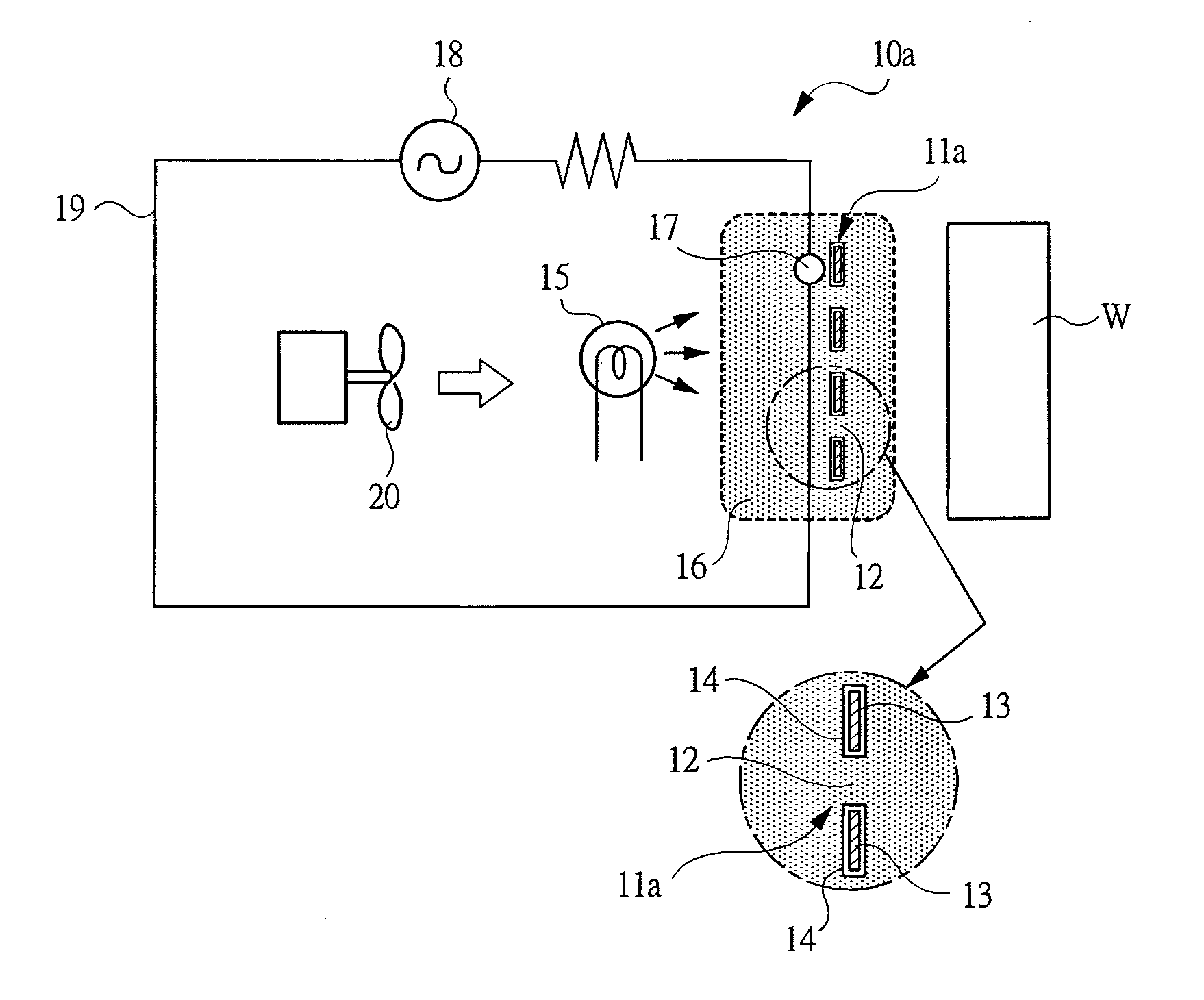
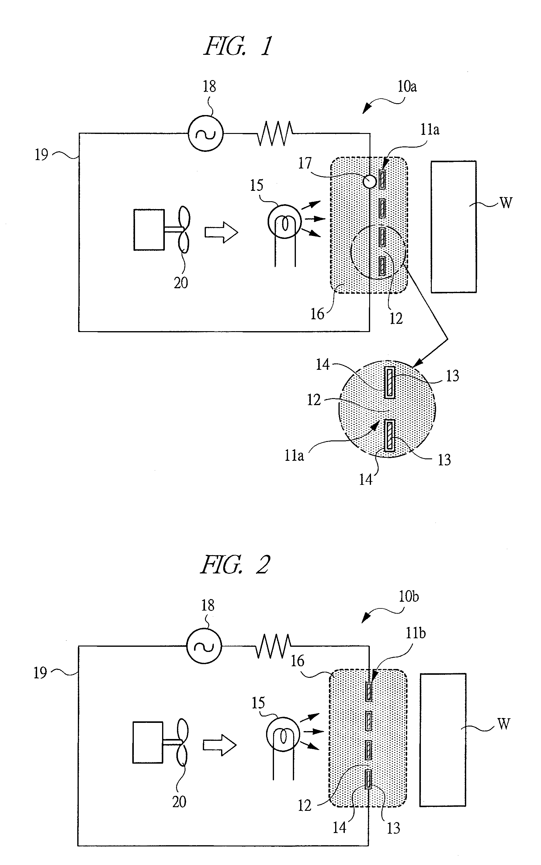
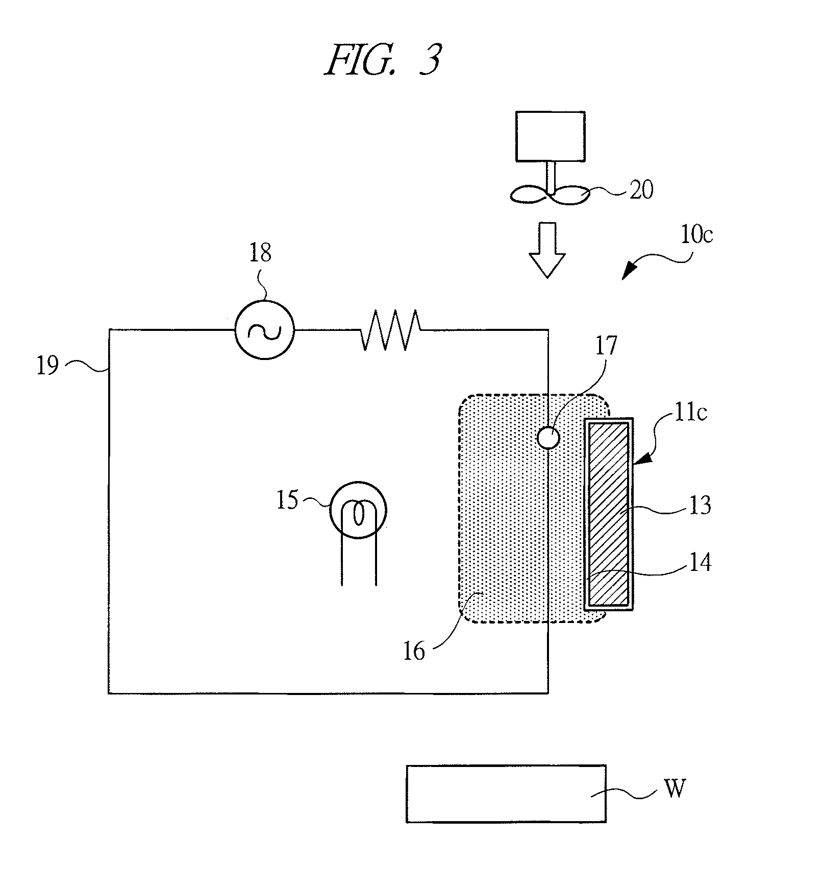
[0027]Hereinafter, embodiments of the present invention will be described in detail with reference to the drawings. FIGS. 1 to 9 are schematic diagrams showing basic structures of ion generators according to embodiments of the present invention, respectively, and the same reference numerals are denoted to members having common functions in these Figures.

[0028]An ion generator 10a shown in FIG. 1 has a photo receiver 11a. The photo receiver 11a comprises a sheet-like or mesh-like base member 13, which is made of a metal net material and has a large number of through-holes 12, wherein a coating layer 14 of titanium oxide (TiO2) is formed on a surface of the base member 13. In order to form the coating layer 14 of titanium oxide on the surface of the sheet-like base member 13, the coating layer 14 of titanium oxide can be generated on the surface of the base member 13 by using the base member 13 as an anode in electrolyte to cause a current to flow. Instead of forming of the coating la...


PUM


Abstract

An ion generator can generate clean ionized gas, in which no foreign matters are mixed, and apply the same to a treated object.
Ultraviolet rays from an ultraviolet generating source 15 are irradiated to a photo receiver 11a provided with a coating layer 14 made of titanium oxide, and air surrounding the photo receiver is electrically separated to generate positively charged particles and negatively charged particles. An electric field is created by the electrode 17 in a space containing the electrically separated air to ionize the charged particles. The ionized charged particles are blown toward the treated object W by a blower 20.

Description

TECHNICAL FIELD[0001]The present invention relates to an ion generator, which blows ionized gas to a treated object and processes the treated object.BACKGROUND ART[0002]When electronic parts such as semiconductor chips are manufactured or assembled, if static electricity occurs to the electronic parts or in jigs used for manufacturing or assembling the electronic parts, manufacturing or assembling work of the electronic parts cannot be performed smoothly. Therefore, by using an ion generator called an “ionizer”, ionized air has been blown to members whose electricity is required to be removed. Charges can be neutralized by supplying the ionized air to each surface of the charged members.[0003]As described in Patent Document 1, a conventional ion generator has a discharge electrode, wherein a corona discharge is caused via air by applying AC voltage to the discharge electrode, and oxygen in air is ionized by an electric field of the corona discharge.Patent Document 1: Japanese Patent...

Claims


Application Information

Patent Timeline
Patent Type & Authority Applications(United States)
IPC IPC(8): B01J19/08
CPCH01T23/00H05F3/04
Inventor IGARASHI, TSUKASA
Owner KOGANEI
Why Eureka
Try Eureka