Method and apparatus for the generation of anionic and neutral particulate beams and a system using same

a technology apparatus, which is applied in the field of apparatus and method for the generation of neutral and anionic particulate beams, can solve the problems of low beam brightness, need for an additional mass filter, and complex source, and achieve the effect of enhancing the yield of negatively charged particles and enhancing the efficiency of electron emission

Inactive Publication Date: 2006-06-08
TECHNION RES & DEV FOUND LTD
View PDF7 Cites 5 Cited by
  • Summary
  • Abstract
  • Description
  • Claims
  • Application Information

AI Technical Summary

Benefits of technology

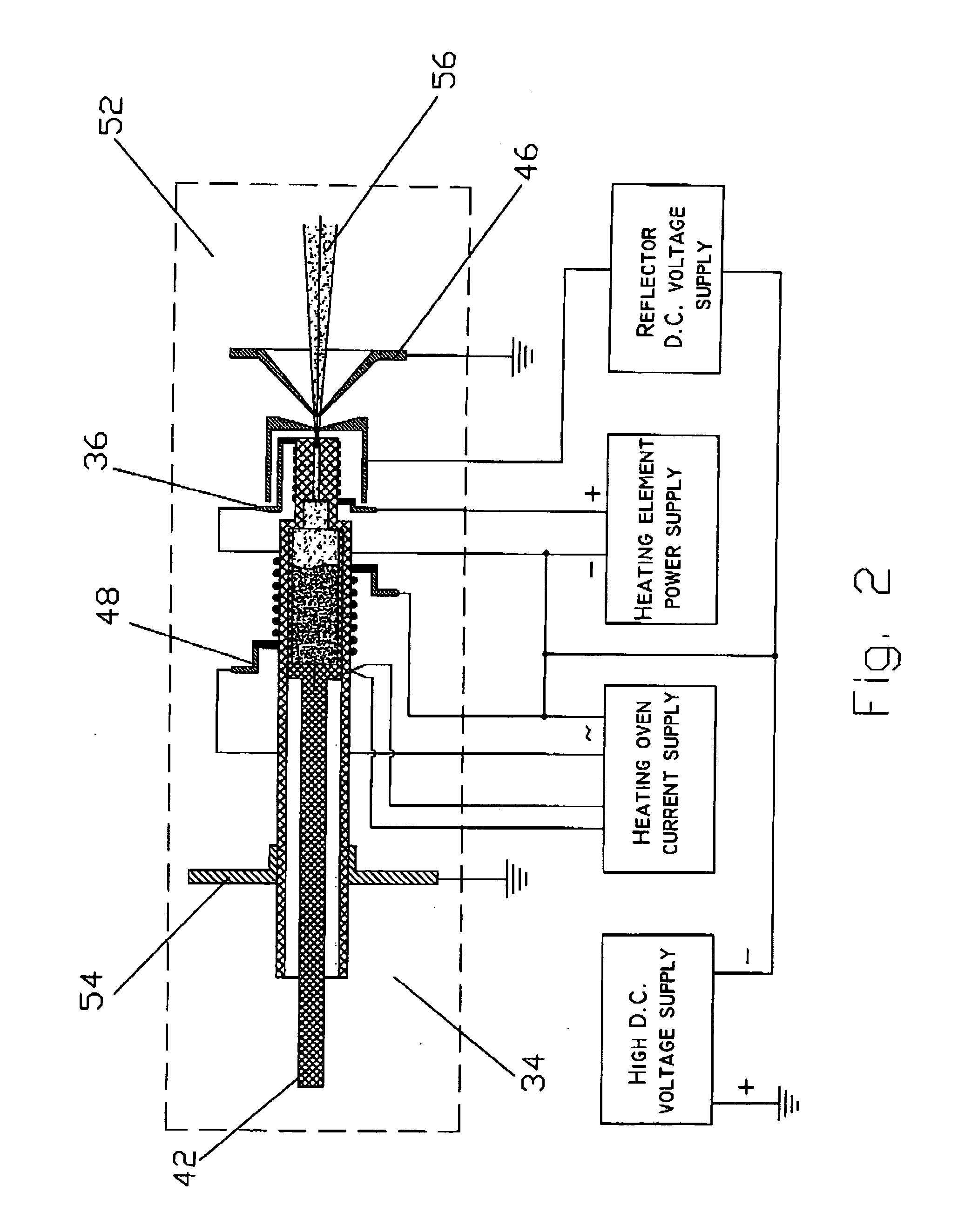
[0047] According to still further features in the described preferred embodiments the method further comprises passing a facilitating agent through the duct in a simultaneous fashion with the electrically neutral particles so as to enhance the yield of said negatively charged particles. According to still further features in the described preferred embodiments, the facilitating agent enhances the efficiency of said electron emission.

Problems solved by technology

These methods have various drawbacks when used for submicron focused beam applications.
Among these are the complexity of the source, the need for an additional mass filter due to fragmentation upon ionization, low current density and brightness, and large energy dispersion of ions or poor focusing.
The main disadvantage of this method is low beam brightness due to the large ionization volume needed to generate high ion current and an inability to introduce a strong electrostatic field into the reaction volume as needed due to strong effects of external fields on trajectories and energy of electrons and depression of the ionization process.
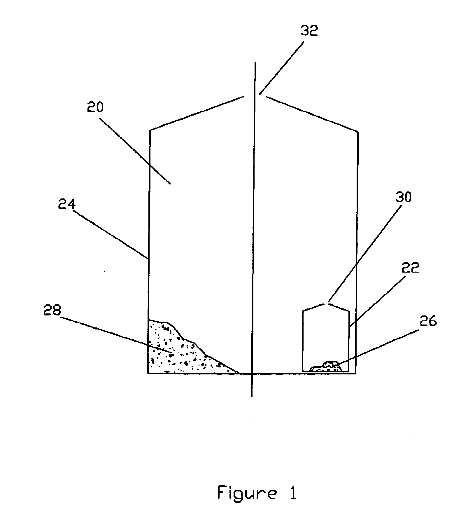
The apparatus of FIG. 1 is disadvantageous for use in microprobe SLMS applications.
Third, the final ion beam current is difficult to control and adjust over a wide range because the ion current continues so long as activator molecules 28 exist in external cell 24.
Fourth, because external and internal cells 22 and 24 arc heated simultaneously using the same oven, it is impossible to efficiently achieve a combined optimal level of fullerene vapor pressure, activator vapor pressure and surface temperature of external cell 24.
Fifth, the apparatus of FIG. 1 is inherently inefficient in using the fullerene powder due to intensive effusion of neutral fullerene molecules through the wide exit orifice 32 and also due to the destruction of a portion of the fullerene molecules by a catalytic reaction by interaction of the fullerenes with the hot nickel surface of external cell 24.

Method used


Image

  • Method and apparatus for the generation of anionic and neutral particulate beams and a system using same
  • Method and apparatus for the generation of anionic and neutral particulate beams and a system using same
  • Method and apparatus for the generation of anionic and neutral particulate beams and a system using same

Examples


examples

[0124] Reference is now made to the following examples, which together with the above descriptions, illustrate the invention in a non-limiting fashion.

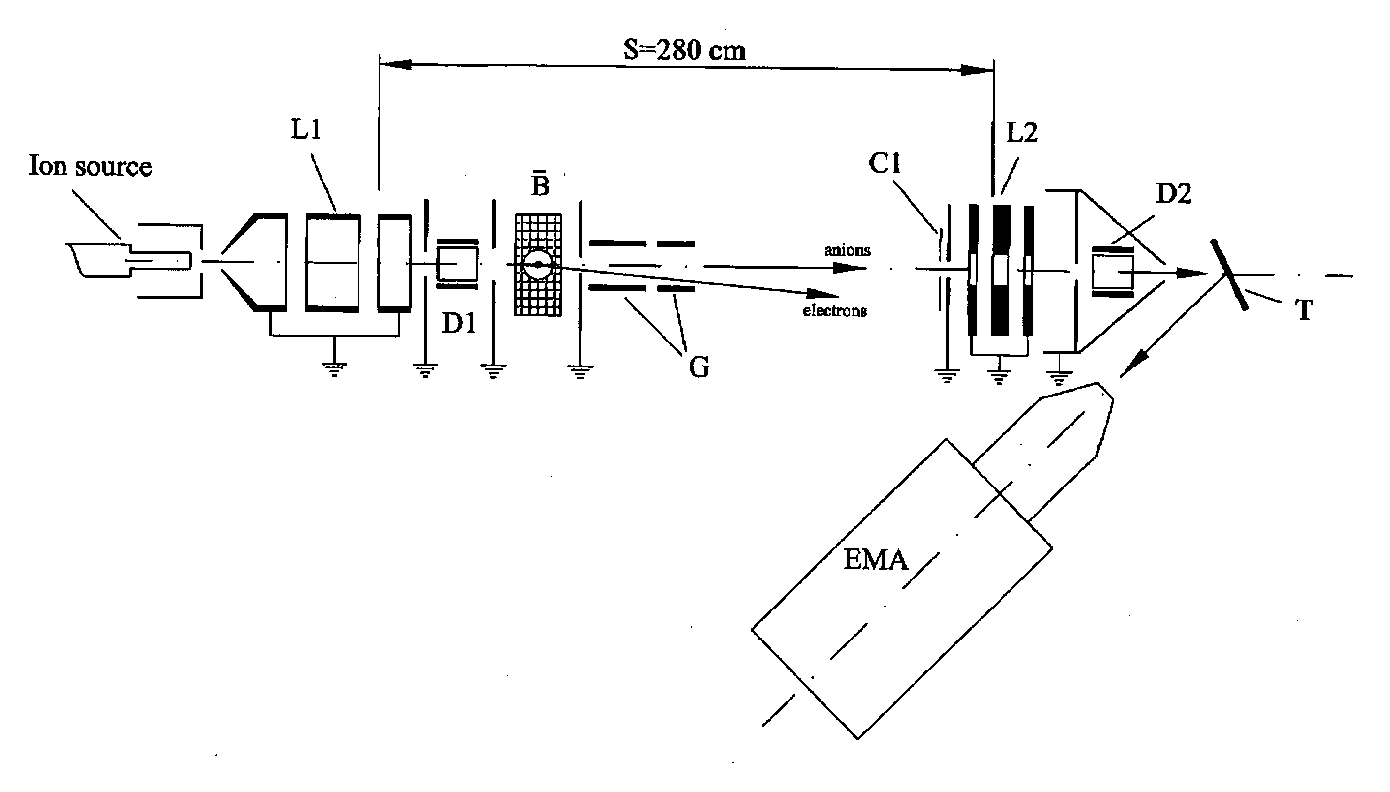
[0125] Reference is now made to FIG. 13, illustrating the relationship of the fraction of neutral fullerene molecules in total flux to the source power and energy of the ion beam, as measured by the system of FIG. 11. The total flux is defined to be the sum of neutral and negative charged molecules. As is illustrated in FIG. 13, the fraction of neutral fullerene molecules in the total flux depends both on the heating power applied to walls 60 (VxA) and on the beam energy (Eo). Eo dependence is attributable to the difference in flight time of the fullerene molecules through the field free region A.

[0126] Reference is now made to FIGS. 14a-14b, in which the mass spectra of anionic fullerene beams, characterized by an Eo=100 eV, are illustrated. The spectra are measured by a quadrupole mass-spectrometer. FIG. 14a illustrates the mass s...


PUM

PropertyMeasurementUnit
temperatureaaaaaaaaaa
melting pointaaaaaaaaaa

Abstract

An apparatus for the generation of anionic and neutral particulate beams is described. The apparatus comprises a duct defined by walls having an inner surface capable of sustaining a temperature above an electron emission temperature of the surface, so as to negatively charge electrically neutral particles being passed through the duct when the surface is heated to the temperature; a heating element for heating the inner surface to the temperature; and an acceleration electrode for ion-optically controlling and manipulating the negatively charged particles into the anion beam. The apparatus may further comprise a protection electrode defining a protected region, which substantially prevent emitted electrons from escaping the protected region. Moreover, a system for analyzing substances ejected from a surface of a sample bombarded with an anion beam generated by the apparatus is described. The system further comprises a detector for detecting the substances once ejected of the surface. Further, a method of generating an anion beam is described.

Description

FIELD AND BACKGROUND OF THE INVENTION [0001] The present invention relates to the generation of particulate beams characterized by high brightness and small emission area, and more particularly, to an apparatus and method for the generation of neutral and anionic particulate beams. Even more particularly, the present invention generates anionic and neutral fullerene beams. The present invention also relates to a method for generating neutral and anionic particulate beams, and more particularly to a method for generating anionic and neutral fullerene beams. The present invention also relates to a system that utilizes a particulate beam for analyzing substances ejected from a surface of a sample bombarded with the particulate beam. [0002] Fullerenes: [0003] Fullerenes, most notably C60, are a newly discovered form of carbon. The fullerenes are a family of hollow (cage) all-carbon structures. C60 is the most prominent member of this family. C60 is a perfectly symmetrical molecule compo...

Claims


Application Information

Patent Timeline
Patent Type & Authority Applications(United States)
IPC IPC(8): H05F3/00C01B31/00B01J19/08
CPCH01J27/20H01J27/26H01J49/14H01J49/16H05H3/02
Inventor KOLODNEY, ELIBEKKERMAN, ANATOLYTSIPINYUK, BORIS
Owner TECHNION RES & DEV FOUND LTD
Why Eureka
Try Eureka