
Data storage devices and methods with frequency-shaped sliding mode control

a data storage device and sliding mode technology, applied in the field of data storage devices, can solve the problems of reducing the data transfer rate affecting data integrity, and affecting the stability of the disk drive, and achieve the effect of improving vibration rejection

Active Publication Date: 2017-01-10
RGT UNIV OF CALIFORNIA +1
View PDF342 Cites 5 Cited by
  • Summary
  • Abstract
  • Description
  • Claims
  • Application Information

AI Technical Summary

Benefits of technology

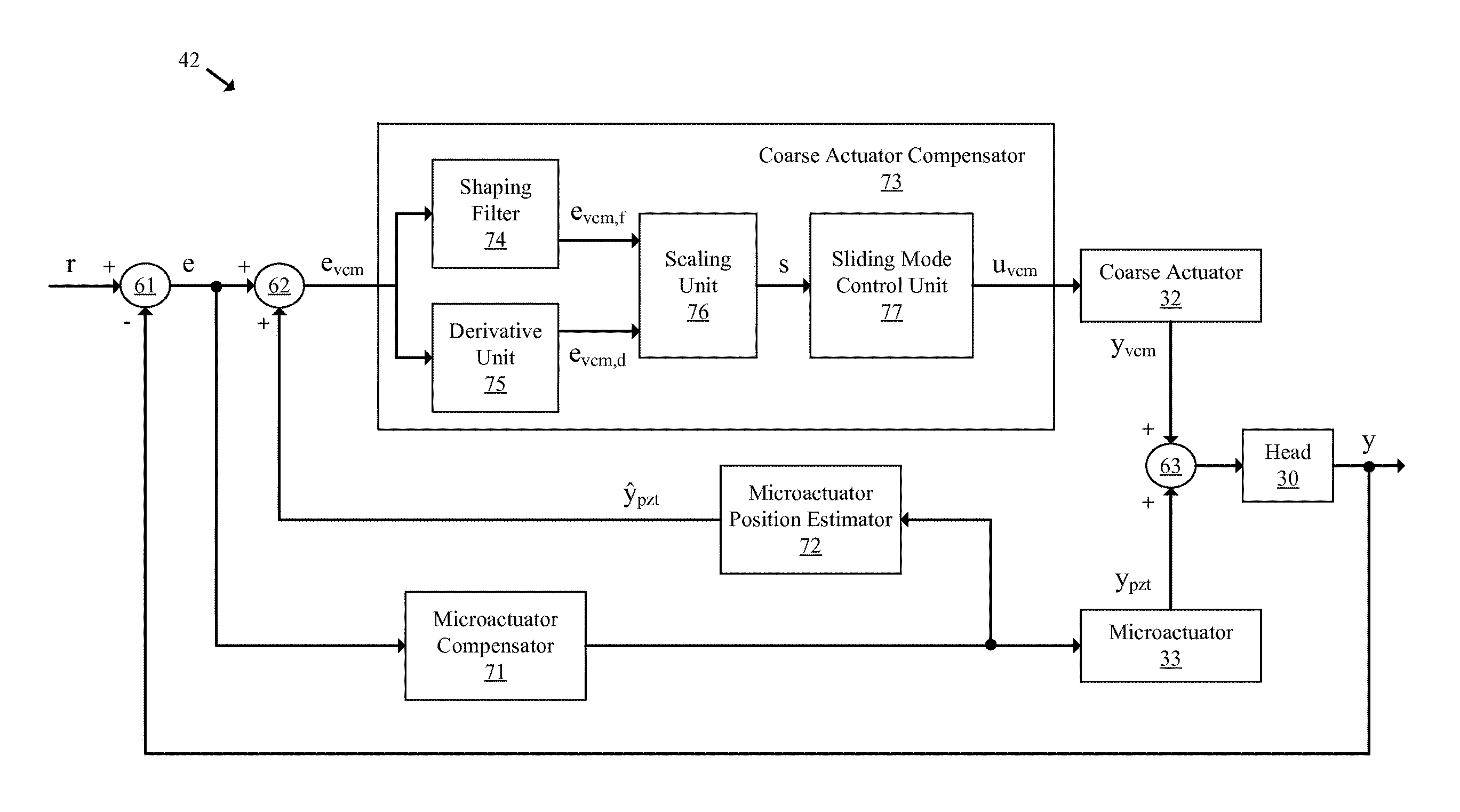
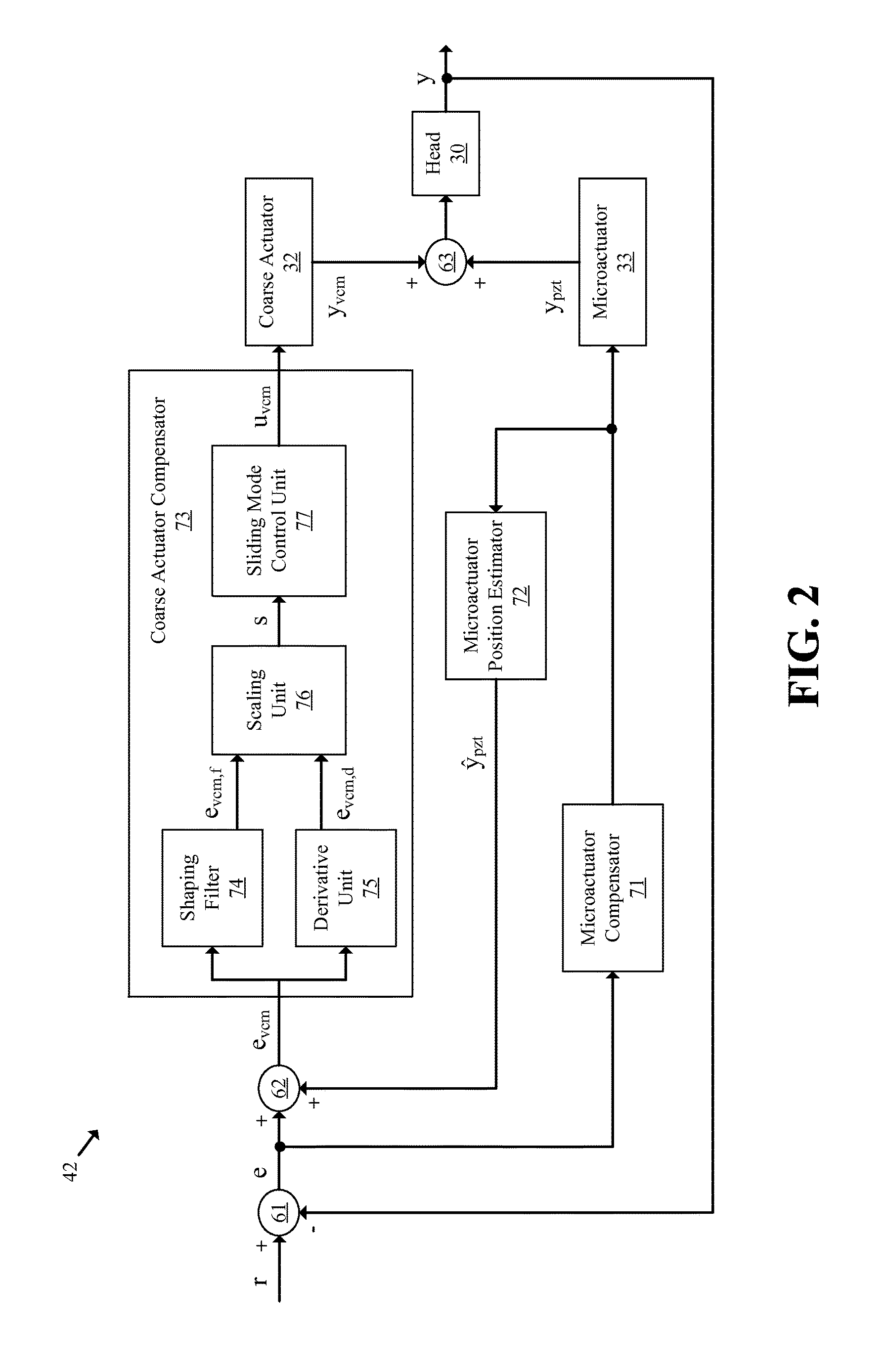
The patent text describes a method for improving the performance of data storage devices by using frequency-shaped sliding mode control to enhance servo controller performance. This control method can be used to make the data storage devices more robust in the presence of external disturbances such as audio vibrations and sudden shock. The frequency shaping is performed using a peak filter that receives a position error signal and amplifies it at customized frequencies. The resulting signal is then used as an input for sliding mode control to pull the head to a desired trajectory. This method provides additional design flexibilities in the frequency domain and improves vibration rejection during track following in the data storage devices.

Problems solved by technology

If the head moves too far from the center of a track during a read operation, the operation must be suspended and retried, which reduces the data transfer rate of the disk drive.
If the head moves too far from the center of a track during a write operation, data integrity may be adversely affected due to existing data on a wrong track being improperly overwritten and potentially lost.
When operating in various environments, a disk drive may be subject to disturbances that affect the head positioning by the servomechanism.
For example, the environment may cause vibrations in the disk drive and there may also be external shocks that act upon the disk drive.
Such vibrations and shocks may cause the actuator arm on which the head is located to oscillate and, thus, to move farther distances away from a track center.
As disk drives become smaller and use lighter actuator arms, the problems caused by external disturbances become a larger concern.

Method used


Image

  • Data storage devices and methods with frequency-shaped sliding mode control
  • Data storage devices and methods with frequency-shaped sliding mode control
  • Data storage devices and methods with frequency-shaped sliding mode control

Examples


Embodiment Construction

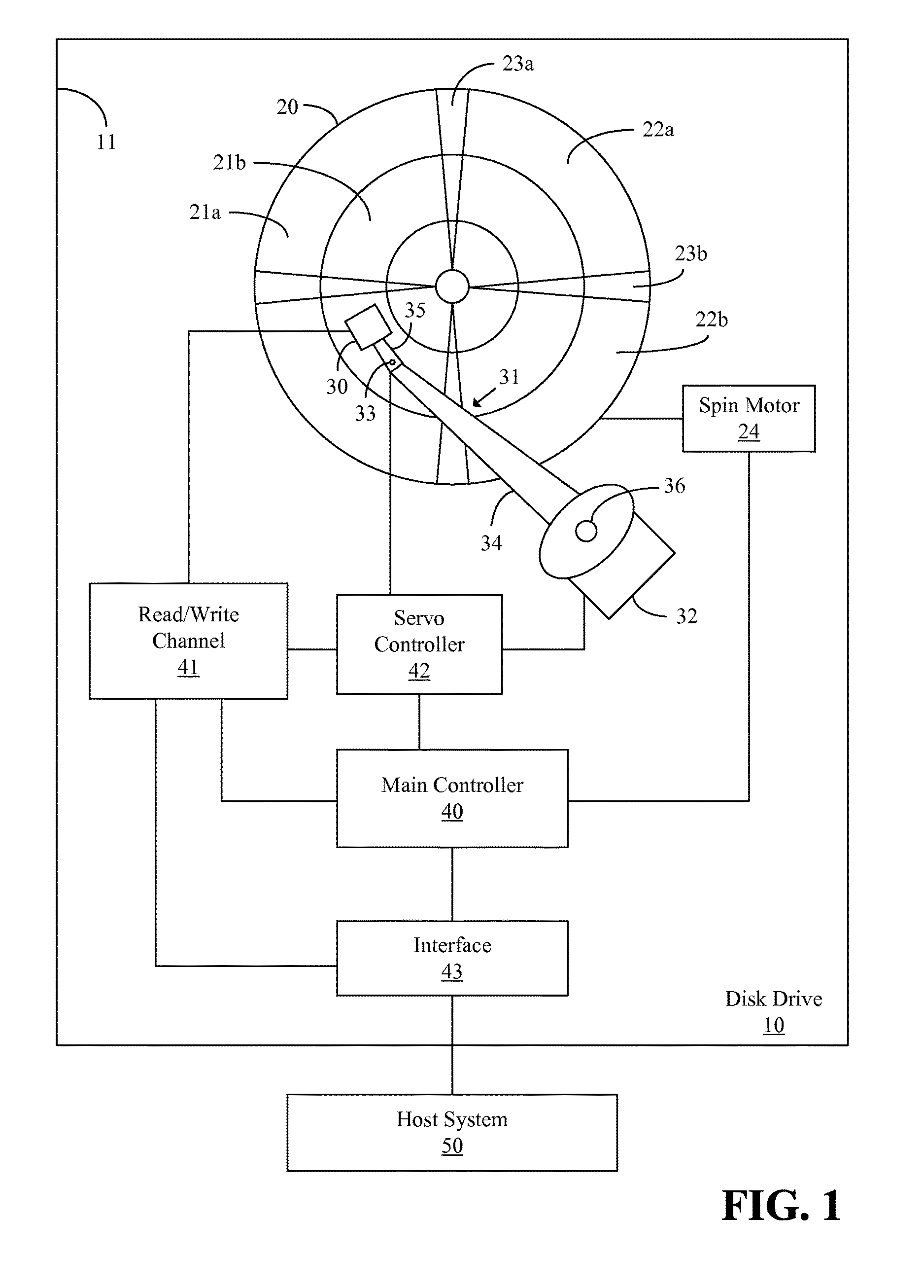
[0025]FIG. 1 illustrates a functional block diagram of a data storage device in an exemplary form of a disk drive 10 of an embodiment of the present invention in communication with a host system 50. The disk drive 10 includes a casing 11, a disk 20, a spin motor 24, a transducer or head 30, an actuator arm assembly 31, a coarse actuator 32, a microactuator 33, a main controller 40, a read / write (r / w) channel 41, a servo controller 42, and an interface 43. The head 30 is mounted on one end of the actuator arm assembly 31, and another end of the actuator arm assembly 31 is connected to a surface (not shown) of the casing 11 of the disk drive 10 by a bearing 36.

[0026]The actuator arm assembly 31 includes a first member 34 and a second member 35 that are interconnected by the microactuator 33. During operation, the spin motor 24 spins the disk 20 around a central axis, and the head 30 reads data from or writes data to a surface of the disk 20. The coarse actuator 32 is configured to rot...


PUM


Abstract

A data storage device includes a disk, a head, a microactuator, a coarse actuator, and a servo controller. The microactuator is configured to position the head relative to the disk. The coarse actuator is configured to position the microactuator relative to the disk. The servo controller is configured to generate an adjusted position error signal based on a position error signal and an estimated microactuator position signal. The servo controller is also configured to filter the adjusted position error signal with a shaping filter to generate a filtered position error signal, and to provide sliding mode control of the coarse actuator based at least partially on the filtered position error signal.

Description

CROSS-REFERENCE TO RELATED PATENT APPLICATIONS[0001]This application claims priority from U.S. Provisional Patent App. Ser. No. 62 / 190,457, filed Jul. 9, 2015, the entire contents of which are incorporated by reference herein.FIELD[0002]Some embodiments of the present invention relate generally to data storage devices such as disk drives and methods and, in specific embodiments, to a data storage device including a coarse actuator, a microactuator, and a servo controller for positioning a head over a disk.BACKGROUND[0003]Data storage devices such as disk drives are commonly used in computers and other electronic devices for the storage and retrieval of data. Disk drives generally include a disk, a head connected to an actuator arm, and an actuator that controls the actuator arm to position the head over the disk. The actuator is usually controlled by a servomechanism that performs the operations of track seek to move the head from one track to another over the disk, and track follow...

Claims


Application Information

Patent Timeline
IPC IPC(8): G11B21/02G11B20/10G11B5/596
CPCG11B5/59627G11B20/10046G11B5/4873G11B5/556G11B5/59622G11B5/59694
Inventor ZHENG, MINGHUITOMIZUKA, MASAYOSHICHEN, XUXI, WEIGUO, GUOXIAO
Owner RGT UNIV OF CALIFORNIA
Learn More