Laminar evaporator

a technology of evaporator and flow, applied in the field of laminar flow evaporator, can solve the problems of unfavorable effect, large temperature gradient, and disadvantage of temperature distribution, and achieve the effect of avoiding additional calorific losses and high current density

Active Publication Date: 2017-01-31
NICOVENTURES TRADING LTD
View PDF48 Cites 10 Cited by
  • Summary
  • Abstract
  • Description
  • Claims
  • Application Information

AI Technical Summary

Benefits of technology

[0017]In accordance with the invention the slot-shaped recesses can be unevenly closely distributed on the heating element surface. By distributing the slot-shaped recesses unevenly a second type of temperature gradient is superimposed on the resistance heating element and / or the porous structure, which overlies the zones with locally distinct temperature gradients and is thus effective over a wider area. More generally formulated, the uneven distribution of the slot-shaped recesses can influence the current and power density distribution. Thus, for example, zones with high current density can be relieved by introducing slot-shaped recesses, since the flow will now go around these zones.
[0018]In a particularly advantageous further development of the laminar evaporator in accordance with the invention, it is provided that the porous structure forms a wick. The capillary action of the wick causes the porous structure to refill automatically in this case with liquid material after pulse evaporation. For this purpose the porous structure only needs to be brought into contact with a source of liquid. The porous structure thus works multi-functionally in this embodiment.
[0019]In addition, the invention relates to an inhaler component, comprising a laminar evaporator in accordance with the invention, as described above, as well as a source of liquid, communicating and / or capable of communicating via capillary with the wick to supply the wick with the liquid substance. It is intended in accordance with the invention that the wick is supplied with the liquid substance in the direction of the lines of flux of the original electric field and the slot-shaped recesses are arranged one behind the other graduated in a row aligned essentially parallel to the lines of flux. The filling of the wick with the liquid substance towards the lines of flux of the original electric field can be more advantageously effected via an electrical contact base so that additional calorific losses can be avoided. By the grouping of the slot-shaped recesses in rows a zone reserved for the wick is produced which, to a large extent, is free of slot-shaped recesses and via which the porous structure can be supplied with the liquid substance to a large extent unhindered. The slot-shaped recesses can also be graduated in several rows.
[0020]As an alternative to the variant arrangement just described, it can also be provided in accordance with the invention that the wick is supplied with the liquid substance transverse to the lines of flux of the original electric field, and the slot-shaped recesses are essentially in the direction of filling. This arrangement has the advantage that the slot-shaped recesses obstruct the capillary liquid flow least, but requires, beside the electrical contacts, a further base for the capillary contact of the wick.

Problems solved by technology

Greater temperature gradients occur in any case in the region of the electrical contacts, where the electric current is introduced into the laminar resistance heating element, and heat flows parasitically into adjacent structural components.
This even temperature distribution can also be a disadvantage, particularly if the material to be evaporated contains components with different boiling points.
This effect is unfavourable if the two materials immediately after their evaporation and / or release are intended to interact with one another in a certain way, in order to give rise, for example, to certain pharmacological and / or pharmacokinetic effects, or to favour such effects.
Free nicotine in base form is, however, readily volatile and in this form hardly accessible to the lungs.

Method used


Image

  • Laminar evaporator
  • Laminar evaporator
  • Laminar evaporator

Examples


Embodiment Construction

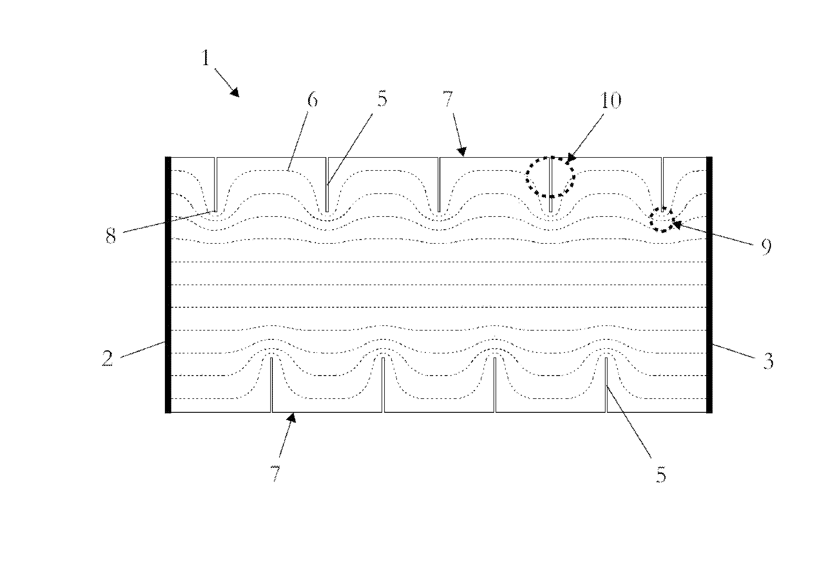
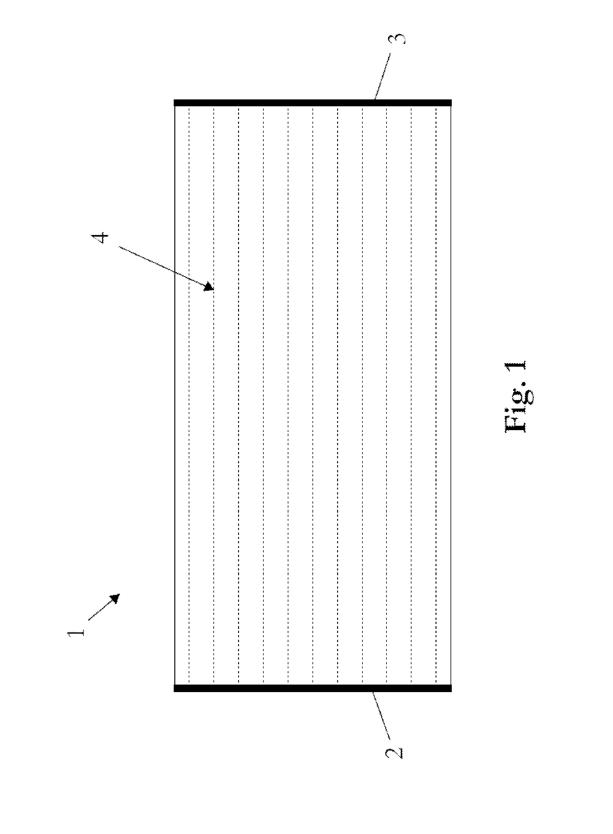
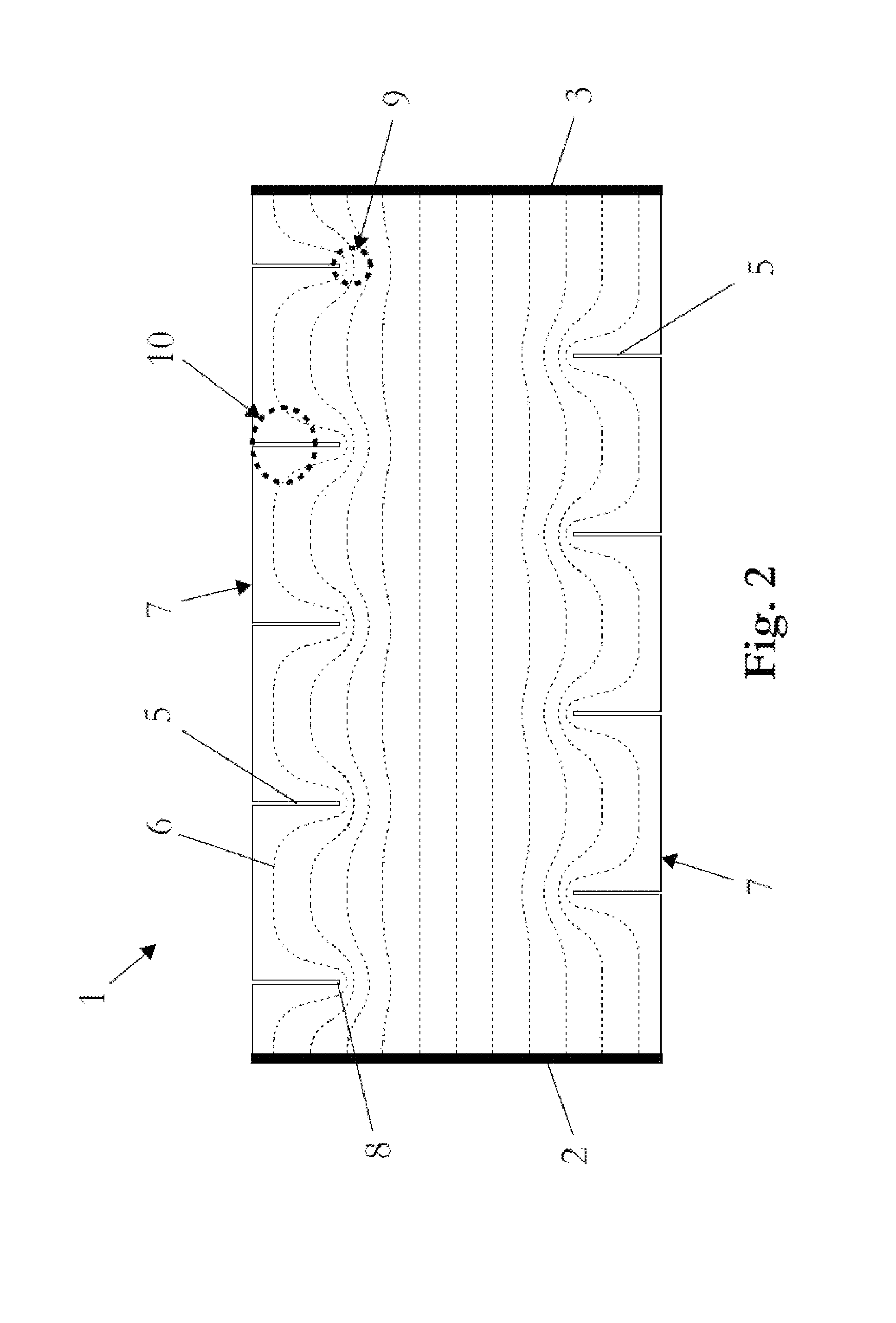
[0034]Table 1 shows the material specifications of an exemplary laminar evaporator in accordance with the invention. According to this the laminar evaporator consists of six layers: a metal foil and five metal wire meshes sintered onto it. The metal in the present example consists of the heat-conducting alloy NiCr8020, DIN material number 2.4869. Different heat-conducting alloys could of course also be used. Heat-conducting alloys can be ordered as starting material from the company ThyssenKrupp VDM GmbH, www.thyssenkruppvdm.de, and then processed into foils, fine wires and wire meshes. ThyssenKrupp VDM GmbH supplies the previously mentioned material NiCr8020, DIN material number 2.4869, under the trade name “Cronix 80”, which can also be fused to a very pure specification with a carbon content <0.02%. The company Record Metall-Folien GmbH, www.recordmetall.de, in co-operation with its suppliers, is in a position to make available metal foils from a thickness of 5 μm from starting m...


PUM


Abstract

The disclosure relates to a laminar evaporator, comprising a laminar electrical resistance heating element for pulse heating and evaporation of an inhalationally receivable material distributed or distributable on the heating element surface by means of an electric heating current flowing or flowable in a laminar manner with at least two electrical contacts and/or poles (2, 3) for introducing the filament current into the resistance heating element, where the resistance heating element has at least one slot-shaped recess (5) constricting the lines of flux (4) of the original electric field forming or formable between the poles (2, 3) and is superficially bonded with an open-celled porous structure holding or capable of holding the material.

Description

[0001]The present application is a 35 U.S.C. §371 National Phase conversion of PCT / AT2011 / 000123, filed Mar. 10, 2011, which claims benefit of Austrian Patent Application No. A 386 / 2010, filed Mar. 10, 2010, the disclosure of which is incorporated herein by reference. The PCT International Application was published in the German language.TECHNICAL FIELD OF THE INVENTION[0002]The invention relates to a laminar flow evaporator, comprising a laminar electrical resistance heating element for pulse heating and evaporation of an inhalationally receivable material distributed or distributable on the heating element surface by means of an electrical heating current flowing or capable of flowing through the resistance heating element with at least two electrical contacts or poles for introducing the heating current into the resistance heating element.BACKGROUND OF THE INVENTIONDefinition of Terms[0003]The term “inhalationally receivable material” covers in principle any material inhalable by...

Claims


Application Information

Patent Timeline
Patent Type & Authority Patents(United States)
IPC IPC(8): A61M15/00A61M11/04A24F47/00A24F40/10A24F40/44A24F40/46
CPCA61M15/00A61M11/041A61M11/042A24F47/008A61M2205/3653A24F40/46A24F40/10A24F40/44A61M2205/8206H05B2203/021
Inventor BUCHBERGER, HELMUT
Owner NICOVENTURES TRADING LTD
Why Eureka
Try Eureka