Supercharge Your Innovation With Domain-Expert AI Agents!

Polycrystalline silicon ingot, preparation method thereof, and polycrystalline silicon wafer

a polycrystalline silicon and ingot technology, applied in the field of semiconductor manufacturing, can solve the problems of low photoelectric conversion efficiency of solar cells produced by such polycrystalline silicon ingots, low quality of polycrystalline silicon ingots obtained by this method, and dislocations caused by dislocations, etc., to achieve good initial nucleation, reduce dislocations, and high quality

Inactive Publication Date: 2017-02-07
JIANG XI SAI WEI LDK SOLAR HI TECH
View PDF2 Cites 0 Cited by
  • Summary
  • Abstract
  • Description
  • Claims
  • Application Information

AI Technical Summary

Benefits of technology

This approach results in polycrystalline silicon ingots with low dislocation density and high quality, enhancing the photoelectric conversion efficiency of solar cells produced from these ingots.

Problems solved by technology

However, since the initial nucleation has not been controlled, the nucleation process is prone to generate dislocations, resulting in disordered crystalline orientations and nonuniform crystalline grains.
Thus the polycrystalline silicon ingot obtained by this method is of low quality.
The photoelectric conversion efficiency of the solar cell produced by such polycrystalline silicon ingot is relatively low.

Method used


Image

  • Polycrystalline silicon ingot, preparation method thereof, and polycrystalline silicon wafer
  • Polycrystalline silicon ingot, preparation method thereof, and polycrystalline silicon wafer
  • Polycrystalline silicon ingot, preparation method thereof, and polycrystalline silicon wafer

Examples


example 1

[0111]A method for preparing polycrystalline silicon ingot.

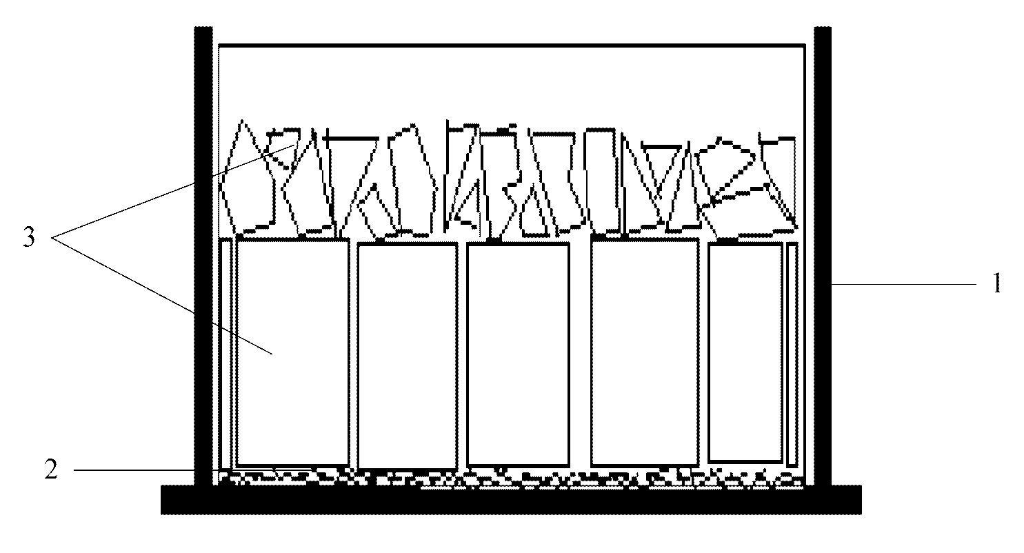
[0112]A layer of silicon nitride was provided on inner wall of a quartz crucible by spray coating, followed by laying a layer of crushed polycrystalline silicon having a size of 1-5 cm at the bottom of the crucible. The layer of crushed polycrystalline silicon was 1 cm. Then various chunk silicon was fed onto crushed polycrystalline silicon until the crucible was full. FIG. 1 is a schematic view of one embodiment, showing the crucible after feeding. 1 is crucible, 2 is crushed polycrystalline silicon and 3 is silicon.

[0113]The crucible filled with silicon was then placed into a casting furnace. Starting a casting ingot program and vacuuming. And the temperature was elevated to the melting point of silicon by heating so as to melt the silicon slowly. During the melting process, solid-liquid interface formed by molten silicon and unmelted silicon was detected by using quartz rob. In preliminary stage of the melting process, th...

example 2

[0120]A method for preparing polycrystalline silicon ingot.

[0121]A layer of silicon nitride was provided on inner wall of a quartz crucible by spray coating. And then a layer of chunk polycrystalline silicon was laid at the bottom of the crucible, followed by laying a layer of crushed polycrystalline material having a size of 1-5 cm. Thickness of the layer of chunk polycrystalline silicon was 1 cm. Thickness of the layer of crushed polycrystalline material was 2 cm. After that, various chunk silicon was fed onto crushed polycrystalline material until the crucible was full.

[0122]The crucible filled with silicon was then placed into a casting furnace. Starting a casting ingot program and vacuuming. And the temperature was elevated to the melting point of silicon by heating so as to melt the silicon slowly. During the melting process, solid-liquid interface formed by molten silicon and unmelted silicon was detected by using quartz rob. In preliminary stage of the melting process, the p...

example 3

[0128]A method for preparing polycrystalline silicon ingot.

[0129]A layer of silicon nitride was provided on inner wall of a quartz crucible by spray coating. And then a layer of graphite plate of high strength, high density and high purity was laid at the bottom of the crucible, followed by laying a layer of crushed polycrystalline material having a size of 1-5 cm. Thickness of the layer of graphite plate was 1 cm. Thickness of the layer of crushed polycrystalline material was 0.5 cm. After that, various chunk silicon was fed onto crushed polycrystalline material until the crucible was full.

[0130]The crucible filled with silicon was then placed into a casting furnace. Starting a casting ingot program and vacuuming. And the temperature was elevated to the melting point of silicon by heating so as to melt the silicon slowly. During the melting process, solid-liquid interface formed by molten silicon and unmelted silicon was detected by using quartz rob. In preliminary stage of the mel...


PUM

PropertyMeasurementUnit
heightaaaaaaaaaa
heightaaaaaaaaaa
heightaaaaaaaaaa

Abstract

Disclosed is a preparation method of a polycrystalline silicon ingot. The preparation method comprises: providing a silicon nucleation layer at the bottom of a crucible, and filling a silicon material above the silicon nucleation layer; heating the silicon material to melt same, adjusting the thermal field inside the crucible to make the melted silicon material to start crystallization on the basis of the silicon nucleation layer; and when the crystallization is finished, performing annealing and cooling to obtain a polycrystalline silicon ingot. By adopting the preparation method, a desirable initial nucleus can be obtained for a polycrystalline silicon ingot, so as to reduce dislocation multiplication during the growth of the polycrystalline silicon ingot. Further disclosed are a polycrystalline silicon ingot obtained through the preparation method and a polycrystalline silicon wafer made using the polycrystalline silicon ingot as a raw material.

Description

CROSS-REFERENCE TO RELATED APPLICATIONS[0001]The present application claims priority to Chinese Application No. 201210096232.2, entitled A Polycrystalline Silicon Ingot, Preparation Method Thereof, and Polycrystalline Silicon Wafer, filed on Apr. 1, 2012, and Chinese Application No. 201210096188.5, entitled Polycrystalline Silicon Ingot, Preparation Method Thereof, and Polycrystalline Silicon Wafer, filed on Apr. 1, 2012, the entire contents of which are hereby incorporated by reference. The present application claims priority to Chinese Application No. 201210096291.X, entitled Polycrystalline Silicon Ingot and Preparation Method Thereof, Polycrystalline Silicon Wafer, and Crucible for Casting Polycrystalline Silicon Ingot, filed on Apr. 1, 2012, and Chinese Application No. 201310033073.6, entitled Polycrystalline Silicon Ingot, Preparation Method Thereof, and Polycrystalline Silicon Wafer, filed on Jan. 29, 2013, the contents of which are hereby incorporated by reference.FIELD OF T...

Claims


Application Information

Patent Timeline
Patent Type & Authority Patents(United States)
IPC IPC(8): C30B11/00C30B29/06C30B11/04C30B11/02C30B28/06H01L29/16C30B11/14H01L29/04
CPCC30B11/003C30B11/00C30B11/006C30B11/02C30B11/04C30B11/14C30B28/06C30B29/06H01L29/04H01L29/16H01L31/182Y02E10/546Y02P70/50H01L21/02002H01L31/03682
Inventor HU, DONGLIHE, LIANGWAN, YUEPENGLEI, QICHEN, HONGRONGZHANG, TAOZHONG, DEJING
Owner JIANG XI SAI WEI LDK SOLAR HI TECH
Features
  • R&D
  • Intellectual Property
  • Life Sciences
  • Materials
  • Tech Scout
  • Unparalleled Data Quality
  • Higher Quality Content
  • 60% Fewer Hallucinations
Learn More