Ignition method for an internal combustion engine and an ignition device operated accordingly

a technology of internal combustion engine and ignition device, which is applied in the direction of engine ignition, generator generated ignition energy, electric ignition installation, etc., can solve the problem that the prior concept or method of stop sampling can be encumbered by residual errors, and achieve the effect of reliable measuremen

Active Publication Date: 2017-02-21
PRUFREX ENG E MOTION
View PDF26 Cites 4 Cited by
  • Summary
  • Abstract
  • Description
  • Claims
  • Application Information

AI Technical Summary

Benefits of technology

[0025]The advantages achieved with the invention are particularly that a reliable measurement can be made by transferring the stop sampling (stop test) temporally into the range of spark formation of an ignition device for an internal combustion engine during the highest possible burn-off current for the contacts of a stop switch, without relevant disturbances in a monitored voltage signal, voltage value, or voltage level occurring at a voltage terminal of the ignition device for the stop switch. Thus, a reliable detection of the switching state, particularly the closed state, of the stop switch is achieved, particularly independently of the employed contact material of the stop switch and / or its switch construction.

Problems solved by technology

Thus, theoretical observations of signal curves in oxidized switch contacts have shown that prior concepts or methods of the stop sampling can be encumbered by a residual error.

Method used


Image

  • Ignition method for an internal combustion engine and an ignition device operated accordingly
  • Ignition method for an internal combustion engine and an ignition device operated accordingly
  • Ignition method for an internal combustion engine and an ignition device operated accordingly

Examples


Embodiment Construction

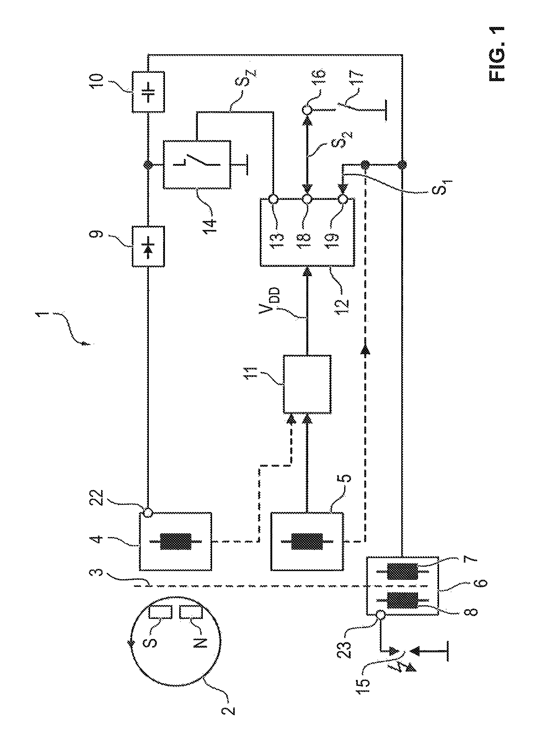
[0036]FIG. 1 shows in a block diagram an ignition device (magnetic or capacitor ignition device) 1 with a magnetic generator 2 in the form of a magnet wheel which has a magnet with a north and south pole N, S and which rotates synchronously with a combustion engine not shown in greater detail. In this case, the magnetic field, generated by magnetic generator 2, amplified by an iron core 3, induces a voltage or a current in a charging coil 4 and optionally in another coil winding or trigger coil 5 and in an ignition transformer 6, often also called an ignition generator or ignition coil, with a primary winding 7 and a secondary winding 8. The positive half waves of a charging voltage (charging current) of charging coil 4 are fed via a rectifier (diode) 9 to a first power storage device 10, called an ignition capacitor hereinafter. The positive half waves of the charging voltage charge ignition capacitor 10 via primary winding (primary coil) 7 of ignition transformer 6, said winding c...


PUM


Abstract

The detection of the switching state of a stop switch at a switch terminal of an ignition device for an internal combustion engine is provided, in which an ignition pulse for controlling an electronic ignition switch is generated and a first power storage device is discharged via an ignition coil and during this discharge a voltage signal having negative and positive voltage half waves is generated, which is used for synchronizing a sampling, representing the switch state of the stop switch, particularly its closed position, of a voltage value at the switch terminal.

Description

[0001]This nonprovisional application claims priority to German Patent Application No. DE 10 2012 021 325.5, which was filed in Germany on Oct. 31, 2012, and to German Patent Application No. DE 10 2012 021 609.2, which was filed in Germany on Nov. 6, 2012, and which are both herein incorporated by reference.BACKGROUND OF THE INVENTION[0002]Field of the Invention[0003]The present invention relates to a method for detecting the switching state of a stop switch at a switch terminal of an ignition device for an internal combustion engine and an ignition device operating accordingly.[0004]Description of the Background Art[0005]It is basically known from DE 197 36 032 B4 and DE 10 2004 059 070 A1 to provide an ignition module or a magnetic ignition circuit (magnetic ignition circuit or condenser ignition device) with an external stop switch. The stop switch acts on power electronics (control unit) and in the closed state prevents the generation of an ignition spark.[0006]In a method discl...

Claims


Application Information

Patent Timeline
Patent Type & Authority Patents(United States)
IPC IPC(8): F02P9/00F02P11/02F02N11/08F02P1/08
CPCF02P9/00F02N11/087F02N11/0866F02P1/086F02P11/02F02N2011/0874F02N2011/0881F02N2011/0896F02P1/08
Inventor LENZ, DENISKIESSLING, LEO
Owner PRUFREX ENG E MOTION
Why Eureka
Try Eureka