Method for treating aluminum slags

a technology of aluminum salt and aluminum slag, which is applied in the field of aluminum salt treatment, can solve the problems of increasing the difficulty of recovering the aluminum portions from the aluminum salt slag, affecting the cooling process, and affecting the recovery process, so as to achieve the effect of improving the cooling process

Active Publication Date: 2017-03-07
AUMUND FORDERTECHN
View PDF8 Cites 0 Cited by
  • Summary
  • Abstract
  • Description
  • Claims
  • Application Information

AI Technical Summary

Benefits of technology

[0014]With the previously noted exemplary embodiments, the advantage is provided that a complete closure of the cooling conveyor against the surrounding atmosphere is provided, whereby in comparison with the alternatively provided housing, a reduction of the inert gas used on the first section of the cooling conveyor is provided. The regulated output of the container contents onto the cooling conveyor leads to a constant layer height as well as a covering of the cooling conveyor over its entire width, so that the cooling process is thereby improved. Based on the double locks provided on the transfer station and the container, only minimal loss of the inert gas that is used can be expected, and as a result, also no release of HF exhaust occurs.

Problems solved by technology

In so far as the waste material is supplied to a further processing step for recovery of the aluminum portion contained therein, the waste materials are underlying after their sloughing off from the bath surface based on the oxidation processes that use the effective surrounding atmosphere, which lead in addition to damaging gases in the working atmosphere of the melting furnace.
Thus, it is known to scrape the waste material into a container and to cool this container under a protective gas atmosphere to a non-dangerous temperature level, which requires a correspondingly large amount of time.
In particular, also these aluminum salt slags increase upon casting of the liquid rough melt to a direct reaction with the surrounding atmosphere, whereby on the one hand, the recovery of the aluminum portions from the aluminum salt slags is made more difficult, and on the other hand, dangerous gasses are released in the working area of the melting furnace.

Method used


Image

  • Method for treating aluminum slags
  • Method for treating aluminum slags
  • Method for treating aluminum slags

Examples


Embodiment Construction

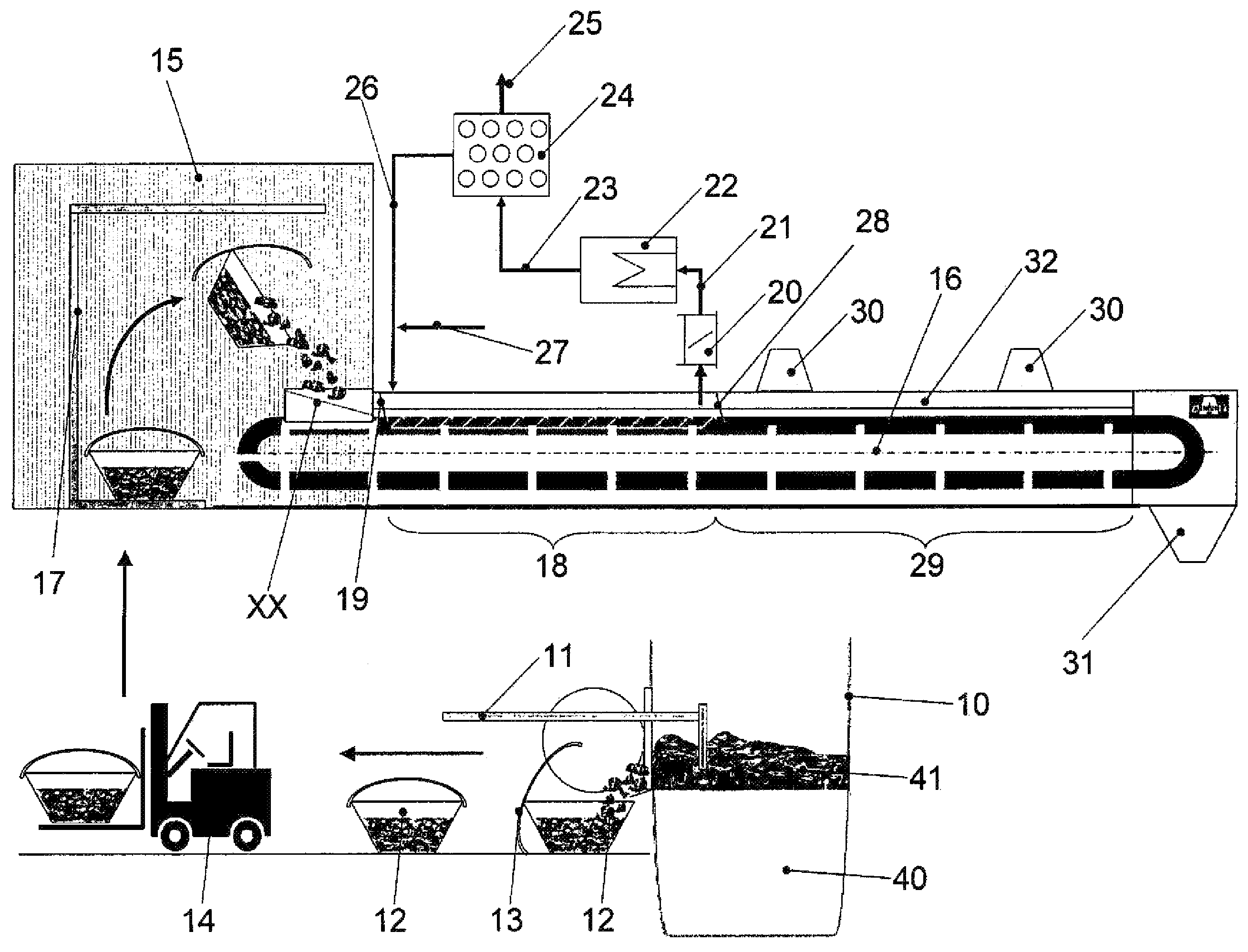
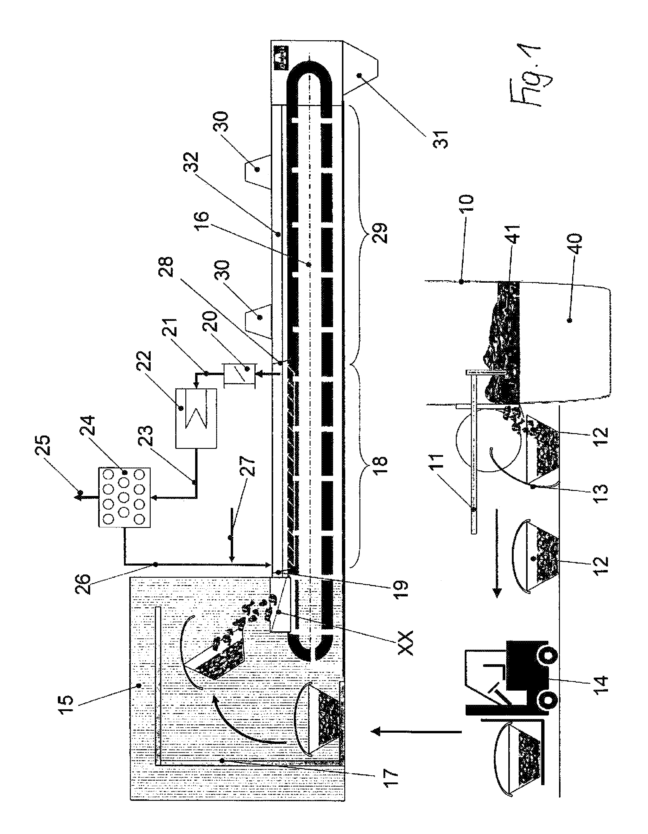
[0022]In a melting furnace 10, by melting down aluminum scrap with the addition of a corresponding salt mixture, a melt 40 of pure aluminum with aluminum slag floating thereon in the form of a so-called aluminum salt slag is provided; the aluminum slag 41 is kept from the melting furnace 10 by means of a scraper or during the casting of the aluminum melt 40 and directly brought into a container 12, which is sealable by means of a cover 13 in a suitable manner against entry of atmospheric oxygen.

[0023]With the exemplary embodiment described in FIG. 1, the container 12 closed by means of the cover 13 is received by a forklift 14 and placed in a housing 15, which likewise is sealed against entry of the surrounding atmosphere. It is understood that for introducing the fork lift 14 into the housing 15, corresponding locks are provided. In the interior of the housing 15, the infeed station 17 of a cooling conveyor 16 connected to the housing 15 is disposed, such that the container 12 can ...


PUM

PropertyMeasurementUnit
temperatureaaaaaaaaaa
metallicaaaaaaaaaa
temperaturesaaaaaaaaaa

Abstract

In a method for treating aluminum slags (41) in the form of dross or aluminum salt slags obtained in the preparation of aluminum, the aluminum slag (41) in the melting process is brought onto a cooling conveyor (16). A first section (18) of the cooling conveyor is flushed with an inert gas and a second section (29) serves for further cooling of the aluminum slag (41) with introduction of air. In the first section (18), the aluminum slag (41) is cooled to a temperature at which the aluminum slag (41) can no longer be chemically changed by exposure to atmospheric oxygen. In the second section (29), the slag is cooled to a temperature at which the cooled aluminum slag (41) can be processed further to recover the aluminum after leaving the cooling conveyor (16).

Description

[0001]The instant application should be granted the priority date of Feb. 25, 2011, the filing date of the corresponding International patent application PCT / EP2011 / 000926.BACKGROUND OF THE INVENTION[0002]The invention relates to a method for treating aluminum slag obtained in the processing of aluminum.[0003]This type of aluminum slag accumulates with the primary product of aluminum as so-called waste material, whereby the slag floating on the surface of the melt is scraped from the aluminum surface of the bath. This waste material contains diverse combustion products and released residue from the furnace infeed of the melting furnace in addition to metallic aluminum and aluminum oxide. According to the portion of aluminum contained in the waste material, the waste material is designated as skimmings (aluminum portion is >45%) or as dross (aluminum portion<45%). In so far as the waste material is supplied to a further processing step for recovery of the aluminum portion conta...

Claims


Application Information

Patent Timeline
Patent Type & Authority Patents(United States)
IPC IPC(8): C22B21/00C22B7/04C22B1/00
CPCC22B21/0007C22B1/005C22B7/04C22B21/0069Y02P10/212Y02P10/20
Inventor MORITZ, MATTHIASNIEDWIEDZ, CHRISTIAN
Owner AUMUND FORDERTECHN
Why Eureka
Try Eureka