Hybrid heat pipe

a heat pipe and hybrid technology, applied in the field of hybrid heat pipes, can solve the problems of difficult to form high-performance wicks in aluminum heat pipes, insufficient heat flux to remove oxide, and inability to form sintered aluminum powder wicks, etc., and achieve high heat flux, high performance, and high performance.

Active Publication Date: 2017-04-11
ADVANCED COOLING TECH
View PDF25 Cites 15 Cited by
  • Summary
  • Abstract
  • Description
  • Claims
  • Application Information

AI Technical Summary

Benefits of technology

[0015]A hybrid heat pipe with capillary grooves and a high performance porous wick provides the following advantages: the high performance evaporator wick is capable of operating at higher heat fluxes as compared to axial capillary grooves and can also operate against gravity on the planetary surface; the condenser's capillary grooves allow the heat pipe to operate in space carry

Problems solved by technology

However, it is difficult to form high performance wicks in aluminum heat pipes, due to the tenacious aluminum oxide layer.
Prev

Method used


Image

  • Hybrid heat pipe
  • Hybrid heat pipe
  • Hybrid heat pipe

Examples


Embodiment Construction

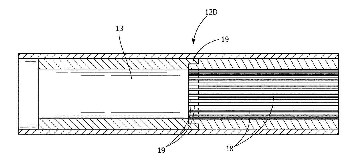
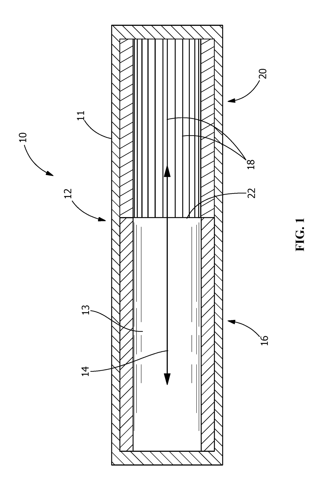
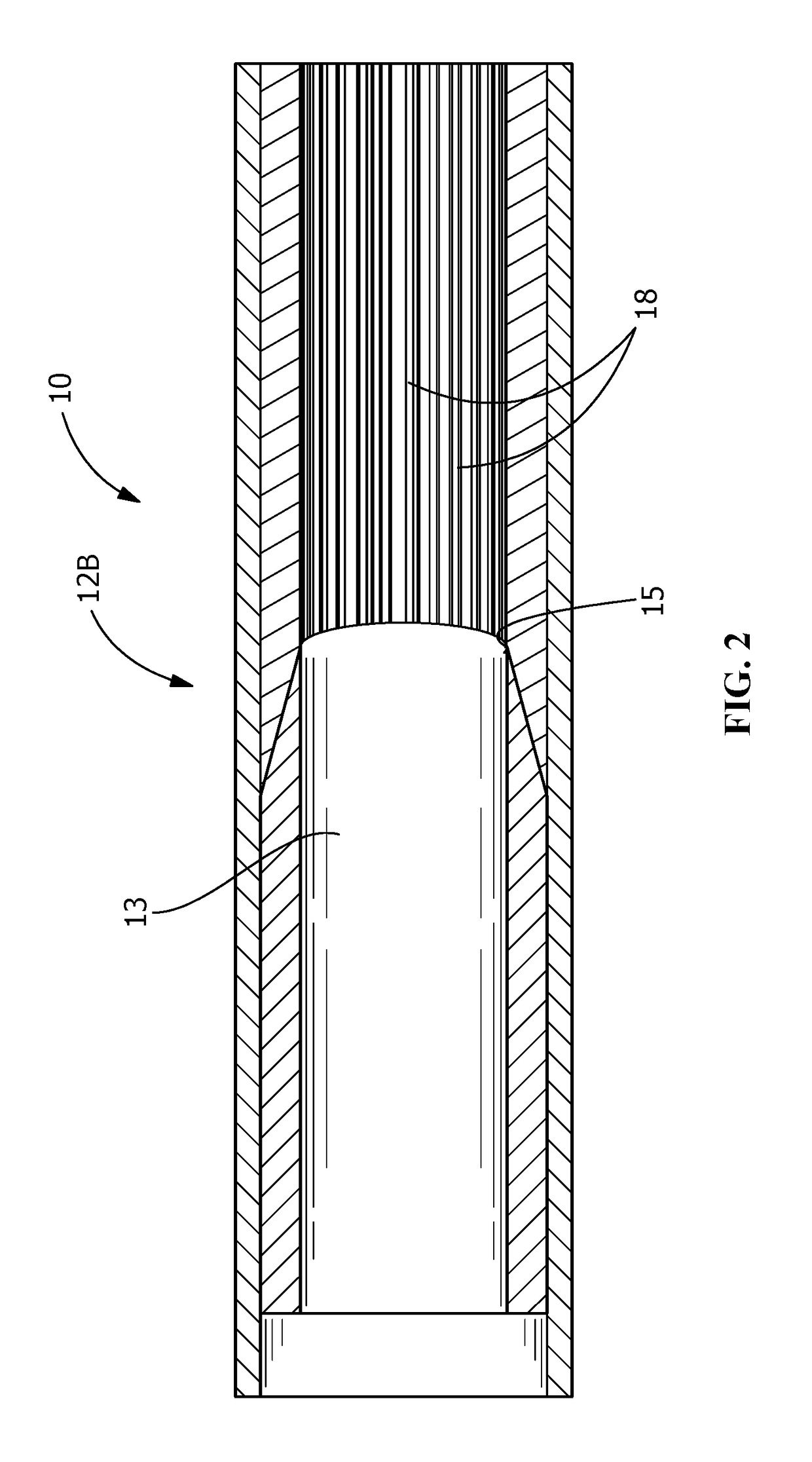
[0023]FIG. 1 is a cross section view of hybrid heat pipe 10 which is a pipe with closed ends. The pipe, which forms the casing of the heat pipe, is made of a heat conductive material which can be metal or some other heat conductive material such as ceramic. Interface 12 is the junction between porous wick 13 in evaporator section 16, and capillary grooves 18 formed in the casing wall of condenser section 20. Parts 11 are the walls of the outermost grooves. Interface 12 is capable of transferring condensed liquid from grooves 18 to porous wick 13, and interface 12 is squared off end 22 of porous wick 13 pressed against grooves 18. Vapor space 14 is located in the central region of heat pipe 10 and is an open passage between condenser section 20 and evaporator section 16.

[0024]The critical requirements for evaporator wick 13 are good fluid connection with capillary grooves 18 and good thermal connection with the wall of evaporator section 16. Instead of forming a higher performance wi...


PUM


Abstract

A heat pipe with a capillary structure that consists of heat conductive capillary grooves in the condenser region that meet with a porous wick in the evaporator section. The embodiments include several structures of the interface at the junction of the porous wick and the capillary grooves. One such interface is a simple butt joint. Others have interlocking shapes on the wick and the grooves such as parts of the wick that fit into or around the grooves.

Description

BACKGROUND OF THE INVENTION[0001]This invention deals generally with heat pipes and more specifically with hybrid heat pipes which have different structures for their evaporator and condenser sections.[0002]Grooved aluminum Constant Conductance Heat Pipes (CCHPs) are the standard heat pipes used in spacecraft thermal control. The capillary grooves, which are typically formed by extrusion, allow long heat pipes that carry high power. On the other hand, the heat pipes have several limitations:[0003]One is that the maximum evaporator heat flux is relatively low, on the order of 5-15 W / cm2. At higher heat fluxes, boiling in the evaporator grooves can disrupt the liquid return, causing the heat pipe to dry out.[0004]Another limitation is the adverse elevation in gravity affected environments, the distance that the evaporator is elevated above the condenser. CCHPs can only operate with a small adverse elevation. They are typically tested on earth with a small adverse elevation of 0.1 inch...

Claims


Application Information

Patent Timeline
IPC IPC(8): F28D15/04
CPCF28D15/046
Inventor ANDERSON, WILLIAM G.HARTENSTINE, JOHN R.VAN RIPER, KYLE S.TARAU, CALINPETERS, CHRISTOPHER
Owner ADVANCED COOLING TECH
Why Eureka
Try Eureka