Endoscope objective lens and endoscope

a technology of endoscope and objective lens, which is applied in the field of endoscope objective lens and endoscope, can solve the problems of difficult production, small diameter and very small edge, and degradation of image resolution performance, and achieve the effects of reducing the diameter good optical performance, and reducing the size of the inserted section

Active Publication Date: 2017-06-13
FUJIFILM CORP
View PDF5 Cites 4 Cited by
  • Summary
  • Abstract
  • Description
  • Claims
  • Application Information

AI Technical Summary

Benefits of technology

[0006]At the distal end portion of the inserted section of an endoscope inserted into the interior of the body of a patient, members such as an illumination section, a surgical tool insertion opening, and an air / water delivering nozzle used to clean the surface of the objective lens, are disposed, besides the objective lens. While such members are disposed at the inserted section, diameter reduction of the inserted section is desired to reduce the burden imposed on the patient when the endoscope is inserted into the interior of the body. To achieve this, further size reduction and diameter reduction of the objective lens are desired. For example, with respect to the objective lenses taught in Patent Documents 1 and 2, further improvement of the entire length of the lens is desired.
[0007]In general, to achieve size reduction and diameter reduction of the objective lens, it is necessary to reduce the entire length and the outer diameter of the lens. To this end, one may consider reducing the number of lenses or the center thicknesses of the lenses. However, reducing the number of lenses has a disadvantage that tendency of aberrations, such as field curvature and lateral chromatic aberration, is increased, resulting in degradation of image resolution performance. Reducing the center thickness also reduces the edge thickness, which is the thickness at the outermost peripheral area of the lens, and particular attention is required for positive lenses, whose edge thickness is smaller than the center thickness. A lens having a small diameter and a very small edge thickness, such as one used as an endoscope objective lens, is difficult to be produced by polishing, and there are limitations in controlling the polishing operation. Further, a single lens having a small edge thickness tends to be inclined during assembly, and the inclined lens hinders achieving desired performance. Therefore an appropriate thickness of the lens is necessary to prevent the lens inclination.
[0008]In view of the above-described circumstances, the present disclosure is directed to providing an endoscope objective lens with reduced size and diameter having good optical performance, and an endoscope provided with the endoscope objective lens.
[0028]The endoscope objective lens of the disclosure is a retrofocus lens having a two-group configuration, includes a cemented lens formed by a positive lens and a negative lens cemented together, and a single lens having a positive refractive power, and satisfies the given condition expressions. This configuration allows achieving the size reduction and the diameter reduction, and achieving good optical performance.
[0029]The endoscope of the disclosure, which is provided with the endoscope objective lens of the disclosure, can achieve the size reduction and the diameter reduction of the inserted section, and can provide a good image.

Problems solved by technology

However, reducing the number of lenses has a disadvantage that tendency of aberrations, such as field curvature and lateral chromatic aberration, is increased, resulting in degradation of image resolution performance.
A lens having a small diameter and a very small edge thickness, such as one used as an endoscope objective lens, is difficult to be produced by polishing, and there are limitations in controlling the polishing operation.
Further, a single lens having a small edge thickness tends to be inclined during assembly, and the inclined lens hinders achieving desired performance.

Method used


Image

  • Endoscope objective lens and endoscope
  • Endoscope objective lens and endoscope
  • Endoscope objective lens and endoscope

Examples


example 1

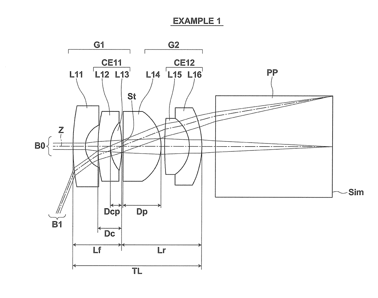
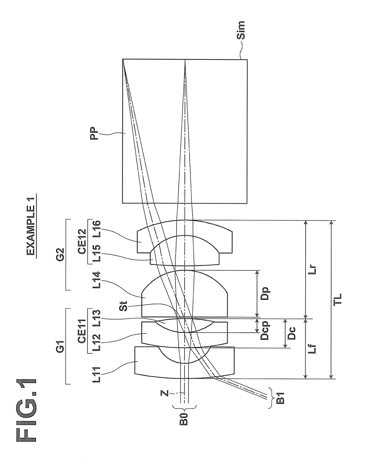
[0091]The lens configuration of and optical paths through an endoscope objective lens of Example 1 are as shown in FIG. 1, and the manner of illustration is as described above. Therefore the same explanations are not repeated here. Tables 1 and 2 show basic lens data and specifications of the endoscope objective lens of Example 1, respectively. In the table of basic lens data, each value in the column of “Si” represents the surface number of the i-th (i=1, 2, 3, . . . ) surface, where the object-side surface of the most object-side element is the 1st surface and the number is sequentially increased toward the image side; each value in the column of “Ri” represents the radius of curvature of the i-th surface; each value in the column of “Di” represents the surface distance between the i-th surface and the i+l-th surface along the optical axis Z; each value in the column of “Ndj” represents the refractive index with respect to the d-line (the wavelength of 587.56 nm) of the j-th (j=1,...

example 2

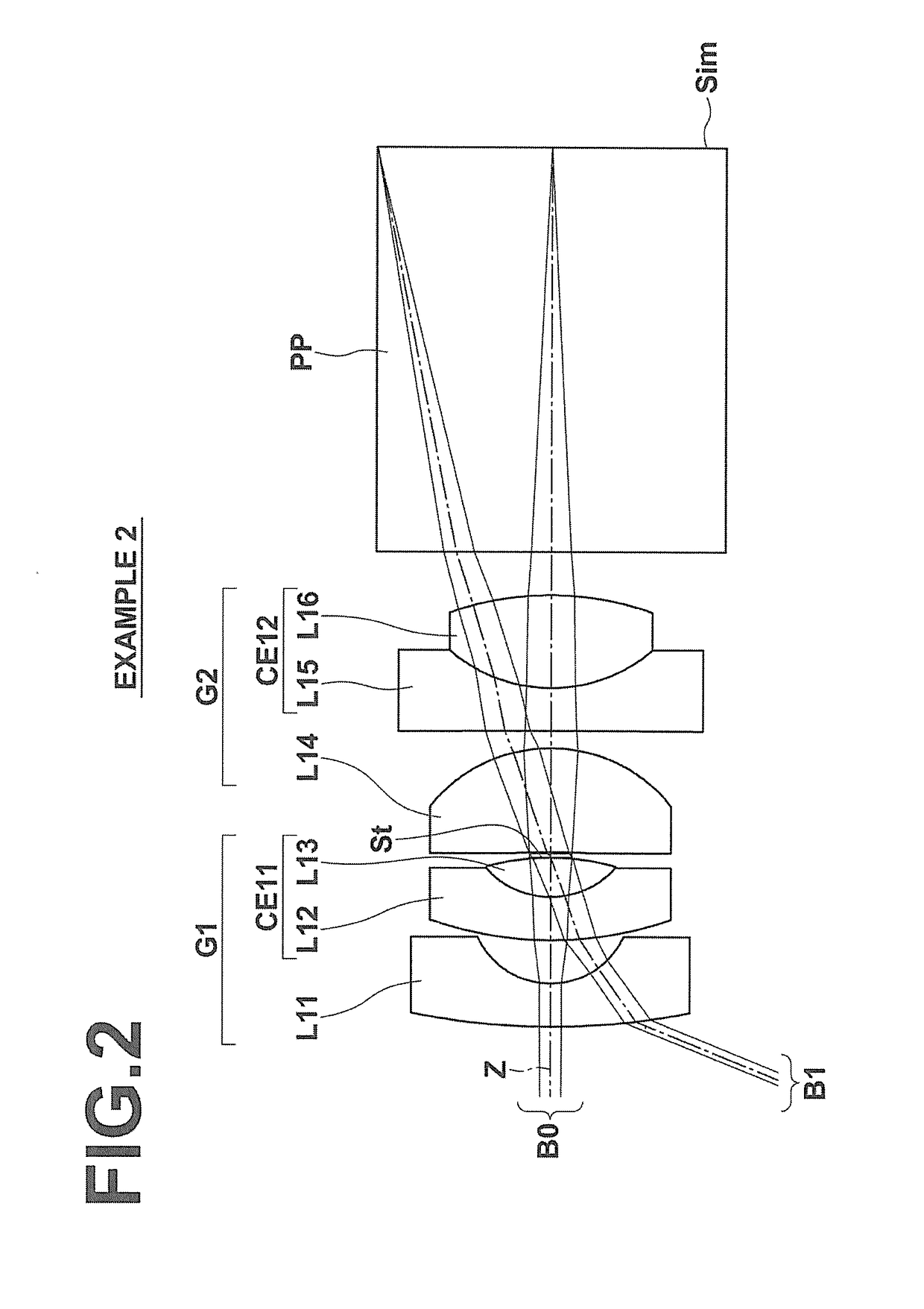
[0098]The lens configuration of the endoscope objective lens of Example 2 is shown in FIG. 2. Tables 3 and 4 show basic lens data and specifications of the endoscope objective lens of Example 2, respectively. FIG. 12 shows aberration diagrams of the endoscope objective lens of Example 2. The values of the basic lens data and the aberration diagrams of Example 2 are those when the object distance is 9.86.

[0099]

TABLE 3Example 2 - Lens DataSiRiDiNdjνdj14.61140.28751.8830040.8020.51090.293132.29880.28751.9200136.0040.54760.26291.6882230.845−1.52340.00006(St)∞0.03697−3.80290.69821.8637524.968−0.97710.11639−158.04770.28751.9200119.00100.98380.61611.6849457.2511−1.93310.290912∞2.71071.5592053.9013∞0.0000

[0100]

TABLE 4Example 2 - Specificationsf1.00Bf1.93FNo.6.702ω[°]134.6

example 3

[0101]The lens configuration of the endoscope objective lens of Example 3 is shown in FIG. 3. Tables 5 and 6 show basic lens data and specifications of the endoscope objective lens of Example 3, respectively. FIG. 13 shows aberration diagrams of the endoscope objective lens of Example 3. The values of the basic lens data and the aberration diagrams of Example 3 are those when the object distance is 9.60. In the basic lens data shown in Table 5, “*” is added to the surface number of each aspheric surface, and a numerical value of the paraxial radius of curvature is shown as the radius of curvature of each aspheric surface. Table 7 shows aspheric coefficients of each aspheric surface. In Table 7, the symbol “E-n” (where n is an integer) following the numerical value of each aspheric coefficient means “×10−n”. The aspheric coefficients are coefficients KA and Am (where m=3, 4, 5, . . . ) in the formula of aspheric surface shown below. The above-explained manner of description of the as...


PUM


Abstract

An endoscope objective lens consists essentially of, in order from the object side, a negative first lens group, a stop, and a positive second lens group. At least one of the first lens group and the second lens includes only one cemented lens which is formed by a positive lens and a negative lens cemented together. The entire system includes a positive single lens. The endoscope objective lens satisfies given condition expressions relating to the focal length of the entire system, the center thickness of the positive single lens, the center thickness of the cemented lens, the distance from the most object-side lens surface to the stop, and the distance from the stop to the most image-side lens surface.

Description

CROSS-REFERENCE TO RELATED APPLICATIONS[0001]The present application claims priority under 35 U.S.C. §119 to Japanese Patent Application No. 2014-136509, filed on Jul. 2, 2014. The above application is hereby expressly incorporated by reference, in its entirety, into the present application.BACKGROUND[0002]Field of the Disclosure[0003]The present disclosure relates to an endoscope objective lens and an endoscope.[0004]Description of the Related Art[0005]In medical field, endoscopes are conventionally used to perform observation, treatment, etc., in the interior of the body of a patient. As an objective lens for use with endoscopes, those disclosed in Japanese Unexamined Patent Publication Nos. 2008-107391 and 2010-276923 (hereinafter, Patent Documents 1 and 2, respectively), for example, have been proposed. Patent Document 1 teaches an endoscope objective lens formed by, in order from the object side, a negative front group, a positive middle group, and a positive rear group. Patent...

Claims


Application Information

Patent Timeline
Patent Type & Authority Patents(United States)
IPC IPC(8): G02B9/04G02B9/00G02B9/08G02B23/24
CPCG02B23/243
Inventor HARADA, KEISUKE
Owner FUJIFILM CORP
Why Eureka
Try Eureka