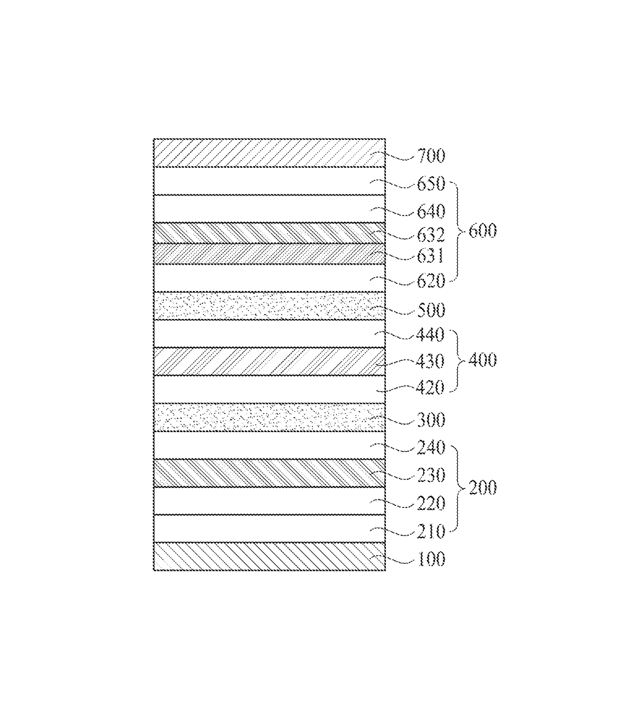
White organic light emitting display device and organic light emitting display apparatus using the same
a light-emitting display and organic technology, applied in the direction of organic semiconductor devices, solid-state devices, semiconductor devices, etc., can solve the problems of low emission efficiency, low emission efficiency, and difficulty in achieving the desired color reproduction ratio, so as to and improve emission intensity and emission efficiency.
- Summary
- Abstract
- Description
- Claims
- Application Information
AI Technical Summary
Benefits of technology
Problems solved by technology
Method used
Image
Examples
first embodiment
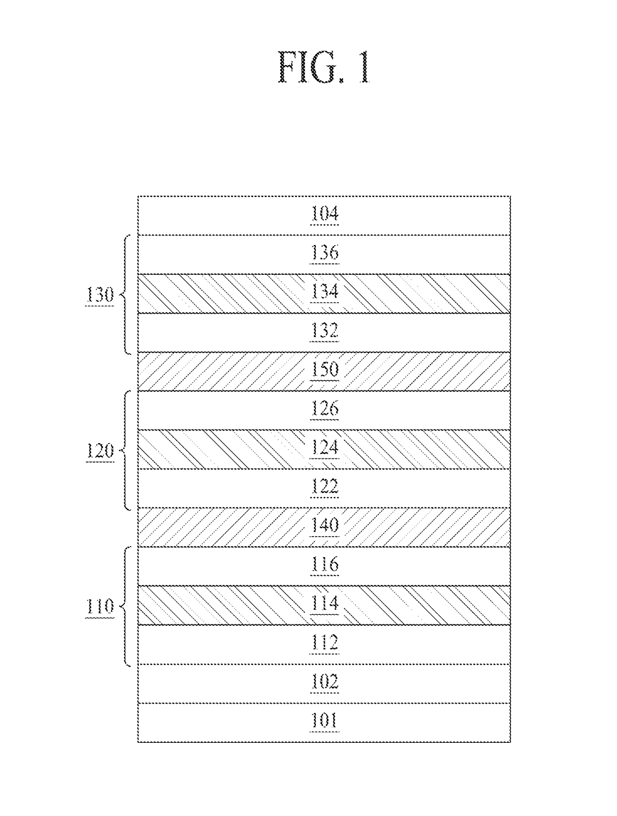
[0090]FIG. 1 is a cross sectional view illustrating a white organic light emitting display device according to the present invention.
[0091]As shown in FIG. 1, the white organic light emitting display device according to the first embodiment of the present invention may include first and second electrodes 102 and 104 on a substrate 101, and first, second and third emitting parts 110, 120 and 130 between the first and second electrodes 102 and 104.
[0092]The first electrode 102 is an anode for supplying a hole, and the first electrode 102 is formed of a transparent conductive material such as TCO (Transparent Conductive Oxide), for example, ITO (Indium Tin Oxide) or IZO (Indium Zinc Oxide), but is not limited to these materials.
[0093]The second electrode 104 is a cathode for supplying an electron, and the second electrode 104 is formed of a metal material, for example, gold (Au), silver (Ag), aluminum (Al), molybdenum (Mo), magnesium (Mg), and etc., or their alloys, but is not limited ...
second embodiment
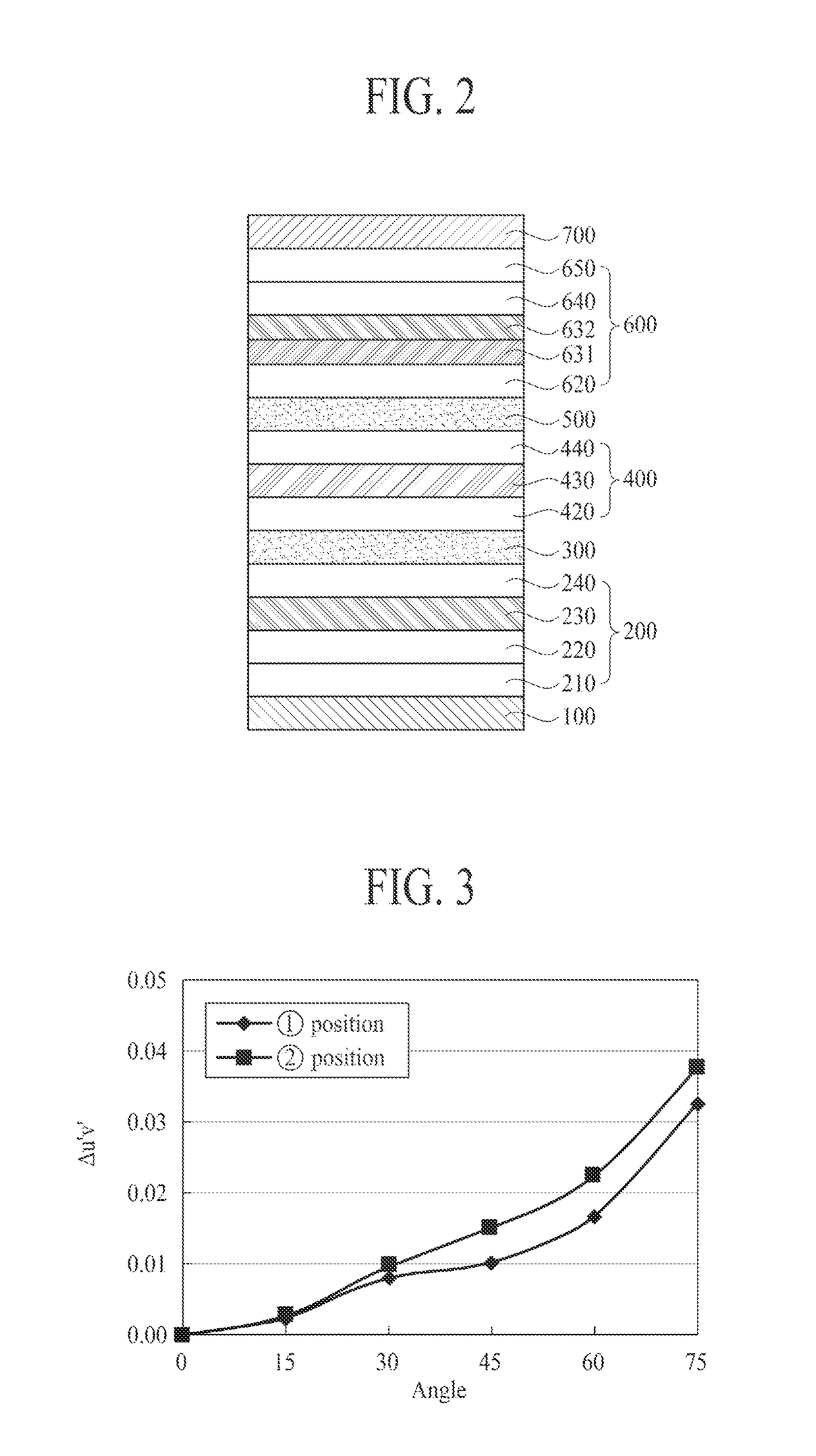
[0139]FIG. 3 illustrates a color shift rate in accordance with a viewing angle according to a position of the emitting part according to the present invention.
[0140]In FIG. 3, a horizontal axis denotes a viewing angle, and a vertical axis denotes Δu′v′.
[0141]FIG. 3 illustrates the color shift rate in accordance with the viewing angle when the red emitting layer is positioned ① under the blue emitting layer, and ② above the blue emitting layer.
[0142]As shown in FIG. 3, while the position ① shows the relatively small color shift rate in accordance with the viewing angle, the position ② shows the relatively large color shift rate in accordance with the viewing angle. From this, it is noted that the position ① has the change of white color smaller than the position ②. For example, in case of the viewing angle 60°, Δu′v′ is 0.0167 at the position ①, and Δu′v′ is 0.0224 at the position ②. Thus, Δu′v′ at the position ① is smaller than Δu′v′ at the position ②.
[0143]According to the results ...
third embodiment
[0167]FIG. 7 illustrates an energy band diagram of an emitting part according to the present invention.
[0168]FIG. 7 illustrates an organic light emitting display device including three emitting parts, wherein the third emitting part includes two emitting layers, that is, red emitting layer (EML) 731 and blue emitting layer (EML) 732. At this time, an organic material having a hole transporting property, that is, a hole transporting layer (HTL) material is applied as a host of the red emitting layer.
[0169]As shown in FIG. 7, a host of the red emitting layer (EML) 731 includes the organic material having the hole transporting property, that is, the hole transporting layer (HTL) material. In the third embodiment of the present invention, an energy band gap of the hole transporting layer (HTL) material is larger than an energy band gap of the host in the red emitting layer (EML) 731, whereby there is a small difference between the energy band gap of the red emitting layer (EML) 731 and ...
PUM
 Abstract
Description
Claims
Application Information
 - R&D
- Intellectual Property
- Life Sciences
- Materials
- Tech Scout
- Unparalleled Data Quality
- Higher Quality Content
- 60% Fewer Hallucinations
Browse by: Latest US Patents, China's latest patents, Technical Efficacy Thesaurus, Application Domain, Technology Topic, Popular Technical Reports.
© 2025 PatSnap. All rights reserved.Legal|Privacy policy|Modern Slavery Act Transparency Statement|Sitemap|About US| Contact US: help@patsnap.com


