Surface contact plug and socket

a surface contact and plug and socket technology, applied in the direction of coupling contact members, coupling device connections, engagement/disengagement of coupling parts, etc., can solve the problems of electrical appliances working abnormally, damage to plugs, sockets, wires and supporting facilities, etc., to increase current transmission capacity, simple structure, and easy operation

Active Publication Date: 2017-06-20
FIRST ELECTRIC ING CHONGQING
View PDF26 Cites 15 Cited by
  • Summary
  • Abstract
  • Description
  • Claims
  • Application Information

AI Technical Summary

Benefits of technology

[0017]To address the problems, the purpose of the invention is to provide a plug and a socket in surface contact characterized by simple structure and easy operation to keep contact pieces in surface contact, so that the contact area is increased, the current transmission capacity is increased, the contact is permanently reliable, and the more frequent the plug and the socket are used, the more reliable the contact is in case of the same volume of the plug and the socket. A contact electrode is designed into a block or circular shape, so that the plug can rotate on the socket, thus the plug can rotate freely without distorting wires, improving the service performance. In addition, the contact pieces are made of a copper material with low cost and good conductivity, reducing the material used and reducing the cost. Furthermore, a safety protection mechanism is arranged in the socket, thus the plug and the socket are absolutely deenergized when hands can touch the contact electrode, and can be energized only when hands cannot touch the contact electrode completely. Therefore, the plug and the socket are very safe for use. Even if metals are inserted into the socket contact pieces, short circuit or electric shock will not occur. Moreover, an overcurrent protection mechanism is arranged in the socket for overcurrent protection, thus effectively avoiding burning out the socket or even fire due to heat in overcurrent transmission.

Problems solved by technology

If the contact resistance R at the plug and socket contact pieces is large, energy will be consumed when high current passes by, heating the contact surface of the plug and the socket, or damaging the plug, the socket, wires and supporting facilities thereof, and even causing a fire in some severe cases.
In addition, the electric appliance will also work abnormally due to insufficient power supply, or be damaged in some severe cases.
As a result, high-performance expensive alloy copper has to be used as materials (e.g., tin-phosphor bronze and beryllium bronze) of the socket contact pieces 2.
However, as fixing parts 2c of the socket contact pieces 2 are only used for fixing and electric conduction, expensive alloy copper materials are not required, resulting in too much waste of precious metals, and increasing the cost.
The contact area S between the plug contact pieces 1 and the socket contact pieces 2 is greatly reduced due to manufacturing process, material, wear, mechanical distortion, environment, heat and looseness of the socket contact pieces 2, resulting in poor contact, and reducing the current transmission capacity.
Although surface contact can be still maintained, the contact area S is reduced by half relatively, resulting in poor contact, and affecting normal operation of the electrical appliances.
During use, the plug contact pieces 1 can be obliquely inserted into the socket, causing mechanical distortion.
Without consideration of materials, environment, flatness and smoothness of the contact pieces, the current transmission capacity in the contact form is greatly reduced compared with that under ideal conditions, thus affecting normal operation of the electrical appliances.
Therefore, slightly large passing current will cause heat and ablation, and even fire.
Although the sockets are adapted to two kinds of plugs, the plugs and the sockets are in line contact, reducing the contact area of the plugs and sockets, and resulting in hidden dangers.
Moreover, as the socket is generally fixed, when the plug and the socket are not aligned during use and the wires are to be rotated, the wires are distorted and then the plug is inserted into the socket.
After doing so for a long term, the joint of the wires and the plug will be damaged, and the circuit will be exposed, resulting in dangers, and the safety is low.
Meanwhile, the contact head 3 needs to have high elasticity, thus expensive nonferrous materials have to be used, increasing the production cost.4. The contact area between the plug contact pieces and the socket contact pieces is limited.
The length or width of the contact pieces is increased to achieve the same current transmission, increasing the contact area S, resulting in waste of nonferrous materials, and increasing the cost.5. For a socket of the prior art, if someone (especially a child) inserts metals into socket holes, electric shock easily occurs.
Some wall sockets are provided with a cover plate at plug holes, so that the plug cannot be inserted into existing single hole, but can be inserted into two holes, resulting in electric shock.
In addition, after the cover plate is provided, a great effort is needed to insert the plug into the socket, thus bringing inconvenient to use of the socket.6. In addition, as the socket of the prior art is not provided with an overcurrent protection mechanism, overcurrent protection capability is unavailable in case of excessive current, heating the contact surface, or damaging the plug and the socket, and even causing a fire in some severe cases.
Moreover, short circuit easily occurs to the socket in high temperature environment, resulting in extremely low safety performance in use.
To sum up, the plug and the socket of the prior art may be worn and deformed with the increased frequency of insertion and unplugging of the plug and the socket, thus resulting in poor contact more easily.

Method used


Image

  • Surface contact plug and socket
  • Surface contact plug and socket
  • Surface contact plug and socket

Examples


example 1

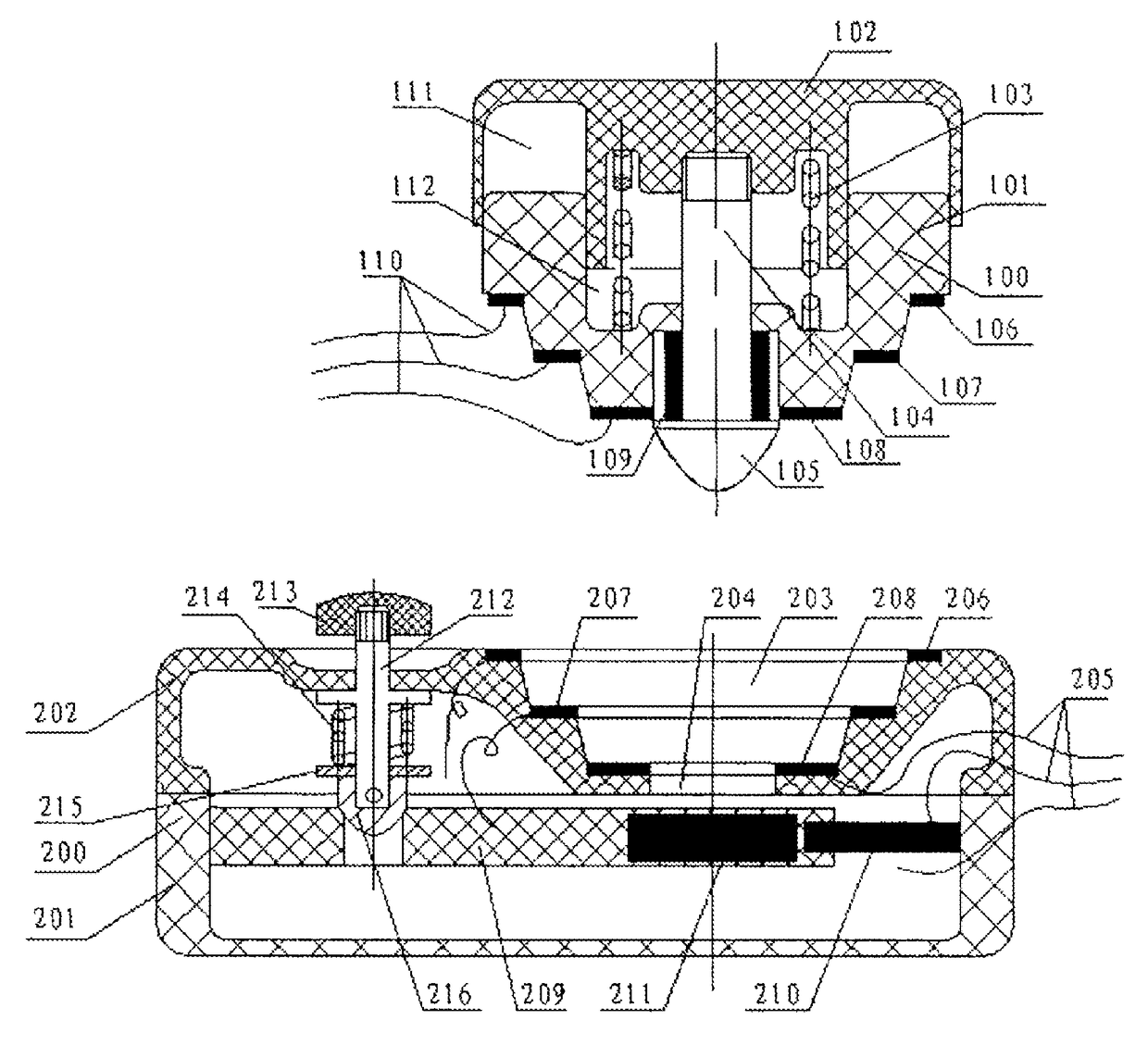
[0066]As shown in FIG. 5, the plug 100 of the invention comprises a lower plug cover 101 and an upper plug cover 102, and the upper plug cover 102 is of a circular structure. A bulge is arranged in the middle of the upper plug cover 102, and forms an upper cover recess 111 with the inner wall of the upper plug cover 102. The upper cover recess 111 is of a circular ring or other structures including rectangular ring and elliptical ring according to the structure of the lower plug cover 101 so that the inner wall of the upper plug cover 102 fits with the outer wall of the upper plug cover 102. When the lower plug cover 101 and the upper plug cover 102 move relative to each other, the top of the upper plug cover 102 can move in the upper cover recess 111. The top of the upper plug cover 102 is provided with a concave structure to form the lower cover recess 112. The lower cover recess 112 has the same shape as the bulge in the middle of the upper plug cover 102. The bulge can move rela...

example 2

[0069]As shown in FIG. 8, the example is similar to example 1, and the difference lies in that as the lower part of the lower plug cover101 is a plane, the plug contact piece 1 is arranged on the bottom surface of the lower plug cover 101. When three wires are used, three plug contact pieces 1 form a concentric ring structure with the lower plug cover 101 as the center. The first plug contract piece 108 is located at the innermost circle of the concentric ring, the third plug contract piece 106 is located at the outermost circle of the concentric ring, and the second plug contract piece 107 is located at the middle circle of the concentric ring. The bottom center of the lower plug cover 101 is a through hole for the clip shaft 104 to stretch out and retract. The inner bottom of the socket recess 203 is a flat bottom recess with a socket through hole 204 at middle. The flat bottom recess is able to fit with the bottom surface of the lower plug cover 101. The socket contact pieces 2 a...

example 3

[0070]As shown in FIG. 10 and FIG. 11, the example is similar to example 2, and the difference lies in that the plug contact pieces 1 are arranged on the bottom surface of the lower plug cover 101. However, the plug contact pieces 1 are not arranged to be concentric ring with a plurality of circles on the bottom surface of the lower plug cover 101, but a plurality of plug contact pieces 1 are uniformly arranged on the same circular ring, so that the plug contact pieces 1 form a fan-shaped structure. On the same circular ring, the gap between two adjacent plug pieces 1 is also a fan-shaped structure, that is, a fan-shaped convex seat 115 with area identical with that of the plug contact piece 1 is formed. When three wires are used, three plug contact pieces 1 are uniformly arranged on the same circumferential ring with the lower plug cover 101 as the center. Two adjacent plug contact pieces 1 are separated by the convex seat 115 with area identical with that of the plug contact piece...


PUM


Abstract

The present invention relates to the technical field of plugs and sockets for electrical appliances. Disclosed are a surface contact plug and socket, comprising a matching plug and socket; a plug contact piece connected with a plug electric wire is arranged on the lower surface of the plug; and a socket contact piece connected with a socket electric wire is arranged on the upper surface of the socket; when the plug is inserted into the socket, the plug contact piece vertically or obliquely meets the socket contact piece to cause surface contact electrification. The surface contact plug and socket of the present invention employ surface contact between contact pieces, enlarge the contact area and improve current transmission capacity since the plug and socket are of the same size, and therefore the contact is always reliable, and the more the plug and the socket are used, the more reliable the contact is.

Description

FIELD OF THE INVENTION[0001]The invention relates to the technical field of plugs and sockets for electric appliances, in particular to a plug and a socket which can rotate relatively.DESCRIPTION OF THE RELATED ART[0002]The current transmission capacity of a plug and a socket is closely related to contact resistance R between plug and socket contact pieces. If the contact resistance R at the plug and socket contact pieces is large, energy will be consumed when high current passes by, heating the contact surface of the plug and the socket, or damaging the plug, the socket, wires and supporting facilities thereof, and even causing a fire in some severe cases. In addition, the electric appliance will also work abnormally due to insufficient power supply, or be damaged in some severe cases. The value of the contact resistance R is closely related to contact area S of the plug and socket contact pieces and pressure P, the larger the contact area S is, the higher the pressure P is, and th...

Claims


Application Information

Patent Timeline
Patent Type & Authority Patents(United States)
IPC IPC(8): H01R13/713H01H36/00H01R13/703H01H37/00H01H13/14H01H37/52H01R24/38H01R13/70H01R13/633H01R13/627H01R13/62H01R13/24H01R24/58
CPCH01R13/713H01H13/14H01H36/0013H01H37/002H01H37/52H01R13/7037H01R13/24H01R13/6205H01R13/6278H01R13/633H01R13/701H01R13/7031H01R13/7137H01R24/38H01R24/58H01R24/46H01R24/48H01R13/62
Inventor LIU, SHUOLIU, ZHONGXIANLIU, ZHONGYU
Owner FIRST ELECTRIC ING CHONGQING
Why Eureka
Try Eureka