Microscopy imaging structure with phase conjugated mirror and the method thereof

a phase conjugated mirror and microscopy technology, applied in the field of microscopy imaging structure, can solve the problems of affecting the application of this method, affecting and affecting the accuracy of microscopy imaging, etc., to achieve the effect of increasing the longitudinal resolution of microscopy imaging

Active Publication Date: 2017-06-27
NAT CENT UNIV
View PDF3 Cites 17 Cited by
  • Summary
  • Abstract
  • Description
  • Claims
  • Application Information

AI Technical Summary

Benefits of technology

[0007]The present invention relates to a microscopy imaging structure with a phase conjugated mirror and a microscopy imaging method using phase conjugation. The microscopy imaging structure with a phase conjugated mirror comprises a first beam splitter, an objective lens and a phase conjugated mirror. The primary objective of the present invention is to achieve detection of a biomedical tissue from only one side of the object and to increase the longitudinal resolution of microscopy imaging.
[0012]II. Scattering of signal light can be reduced to increase the biomedical imaging efficiency;

Problems solved by technology

However, the most prominent problem with the method is that the thickness and shape of the object to be detected may seriously interfere the application of this method.
Once the object to be detected has a volume too bulky, illuminating the probe beams from both sides of the object will become difficult and sometimes may even become impossible.

Method used


Image

  • Microscopy imaging structure with phase conjugated mirror and the method thereof
  • Microscopy imaging structure with phase conjugated mirror and the method thereof
  • Microscopy imaging structure with phase conjugated mirror and the method thereof

Examples


first embodiment

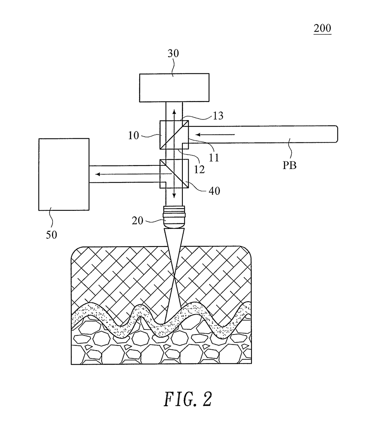
[0033]As shown in FIG. 2, an embodiment of a microscopy imaging structure 200 with a phase conjugated mirror of the present invention comprises a first beam splitter 10, an objective lens 20 and a phase conjugated mirror 30.

[0034]The first beam splitter 10 has a first input end 11, a first light guide end 12 and a first output end 13. Firstly, a coherent laser beam is input through the first input end 11 as a probe beam PB, which is then output to an objective lens through the first light guide end 12. Then, a signal light is received by the objective lens through the first light guide end 12 again. Finally, the received signal light is output to the phase conjugated mirror 30 through the first output end 13.

[0035]The objective lens 20 is disposed in a light path of the first light guide end 12. The objective lens firstly receives the probe beam PB output from the first light guide end for projection into an object, such as a human tissue, to be detected, and then receives the signa...

second embodiment

[0039]As shown in FIG. 3, this embodiment is mainly configured according to the first embodiment, with the phase conjugated module 30 of this embodiment being a phase conjugated mirror 30.

[0040]The phase conjugated mirror is commonly used in the filed of imaging technologies. The recording medium of the phase conjugated mirror mostly lithium niobate crystals, barium titanate crystals, and photorefractive crystals and so on. When a reference beam RB is introduced to generate interference with the signal light in the phase conjugated mirror, interference patterns can be recorded by the crystals of the phase conjugated mirror.

[0041]When a conjugated reference beam RB* is introduced into the crystals, a conjugated signal light will be diffracted by the crystal. The conjugated signal light is then projected into the biomedical tissue by the objective lens to generate a conjugated probe beam PB* which is focused in the reverse direction of the probe beam PB.

[0042]For the interference patt...

third embodiment

[0043]As shown in FIG. 4, in the embodiments of the first and the second embodiments, a spatial light modulator 60 may further be introduced in the light path of the first input end 11. The spatial light modulator 60 is adapted to modulate the initial phases of the probe beam to reduce scattering of the biomedical tissue to be detected so that the probe beam can be focused to a deeper position and the energy is more concentrated. This also increases the efficiency of microscopy imaging of the biomedical tissue.


PUM

PropertyMeasurementUnit
microscopyaaaaaaaaaa
phase conjugatedaaaaaaaaaa
microscopy imagingaaaaaaaaaa

Abstract

The present invention discloses a microscopy imaging structure with phase conjugated mirror and the method thereof. The afore-mentioned imaging structure produces a reverse focusing conjugated probe beam together with an original probe beam. These two probe beams meet at the focal point in the object body to be probed, and an interference pattern is produced. The interval between any two consecutive wave fronts in the interference pattern is then half of the wavelength of the original probe beam, and hence the vertical resolution of the image is improved. The present invention also applies a light modulator module on the probe beam to easily adjust the depth of the focal point of the probe beam and the phase conjugated reverse focusing probe beam in the object body. With the adoption of this invention, the size or position limitation of the target object is eliminated and the imaging resolution is also improved.

Description

BACKGROUND OF THE INVENTION[0001]1. Technical Field[0002]The present invention relates to a microscopy imaging structure with inverse focus by a phase conjugated mirror and a microscopy imaging method using inverse focus by phase conjugation, and more particularly, to a microscopy imaging structure with inverse focus by a phase conjugated mirror and a microscopy imaging method using inverse focus by phase conjugation which are used for probing human tissues in the field of medical treatments.[0003]2. Description of Related Art[0004]FIG. 1 is a diagram illustrating a prior art biomedical detection imaging structure. This is a method commonly used for increasing the imaging resolution of biomedical tissue imaging apparatuses currently available. As shown in FIG. 1, the prior art biomedical detection imaging structure forms an image mainly by penetrating a probe beam through a biomedical tissue for the probing purpose or by exciting a phosphor which is injected into an object to be det...

Claims


Application Information

Patent Timeline
Patent Type & Authority Patents(United States)
IPC IPC(8): H04N7/18G02B21/16G02B21/14G02B21/36G02B21/08G02B21/00G01N21/45A61B5/00
CPCG01N21/45G02B21/0056G02B21/082G02B21/14G02B21/16G02B21/365A61B5/0059
Inventor SUN, CHING-CHERNGYU, YEH-WEILIN, CHE-CHUCHEN, SZU-YU
Owner NAT CENT UNIV
Why Eureka
Try Eureka