Receiver for receiving data in a broadcast system

a technology for receiving data and broadcast systems, applied in the field of receivers, can solve problems such as decoding errors, and affecting the accuracy of data reception, and achieve the effect of increasing the probability of error-free reception/reconstruction and increasing the cos

Active Publication Date: 2017-06-27
SATURN LICENSING LLC
View PDF42 Cites 29 Cited by
  • Summary
  • Abstract
  • Description
  • Claims
  • Application Information

AI Technical Summary

Benefits of technology

[0017]It is an object to provide a receiver for receiving data in a broadcast system and a corresponding broadband server for providing redundancy data that enable to further increase the probability of error-free reception / reconstruction of broadcast data without increasing the costs for transmitting too many redundancy data. It is a further object to provide corresponding methods, a broadcast system, as well as a corresponding computer program for implementing said methods and a non-transitory computer-readable recording medium for implementing said methods.
[0043]One of the aspects of the disclosure is to make use of the known concept of using redundancy data (in the known system obtained via a unicast system, but generally obtainable via a broadband system) and to further define in which way the optimal amount of redundancy data can best be obtained. This avoids a waste of available resource if only the minimal amount of necessary redundancy data is transmitted.

Problems solved by technology

Subscribers located at the edge of the coverage area of a broadcast system (also called broadcast network) are suffering from low receptions levels, which may hinder error-free decoding.
Furthermore other channel impairments like burst noise or narrowband interferer create decoding errors in a sheer broadcast reception scenario which are corrected with the additional redundancy data stream.

Method used


Image

  • Receiver for receiving data in a broadcast system
  • Receiver for receiving data in a broadcast system
  • Receiver for receiving data in a broadcast system

Examples


Embodiment Construction

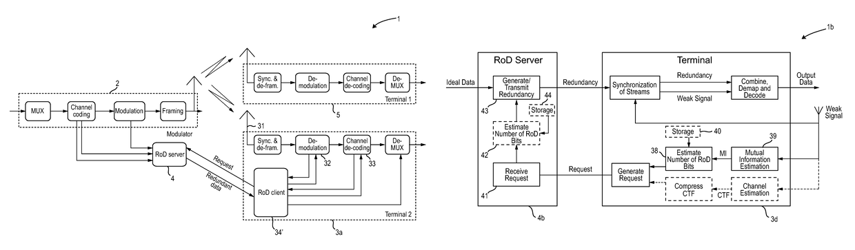
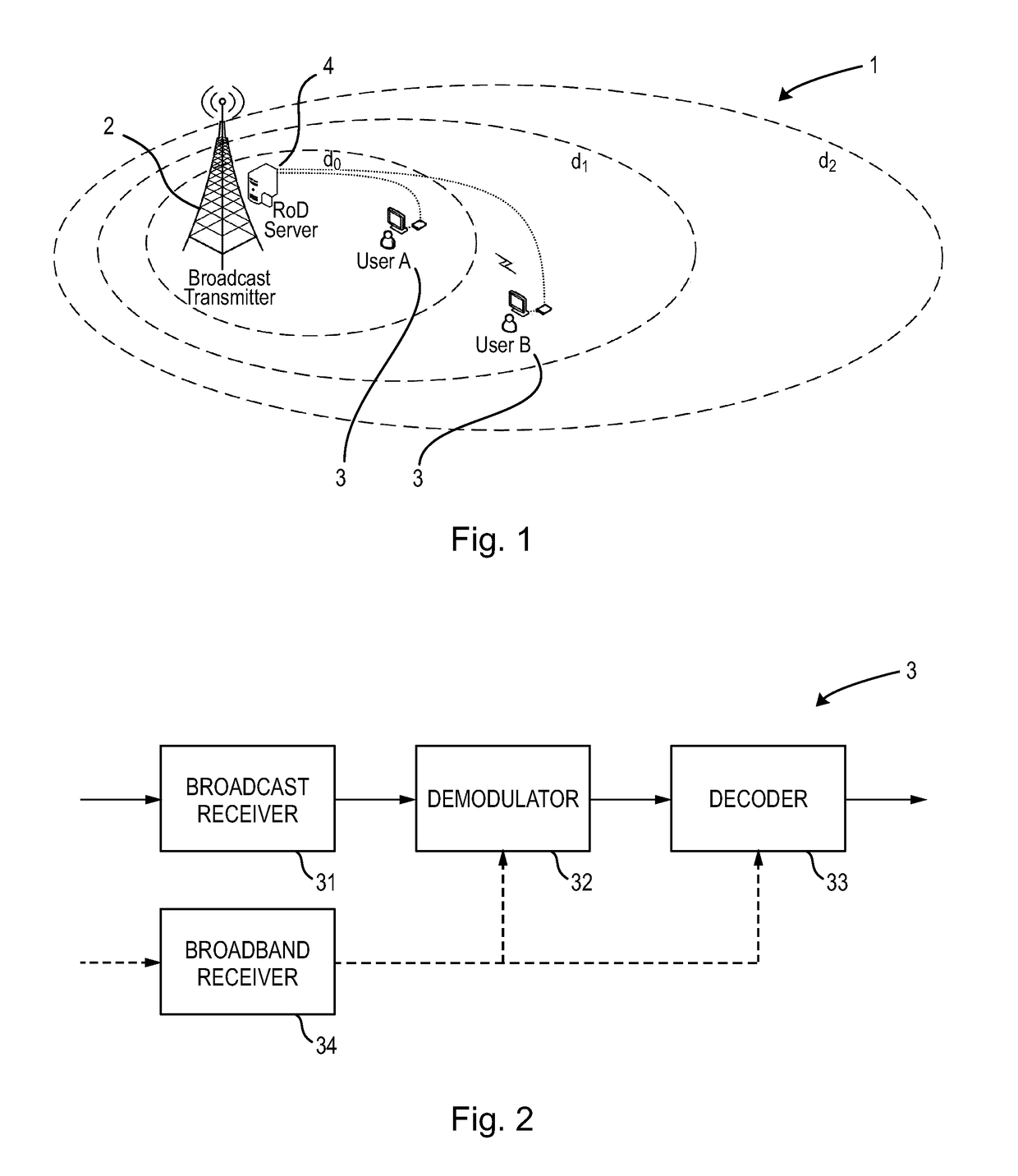
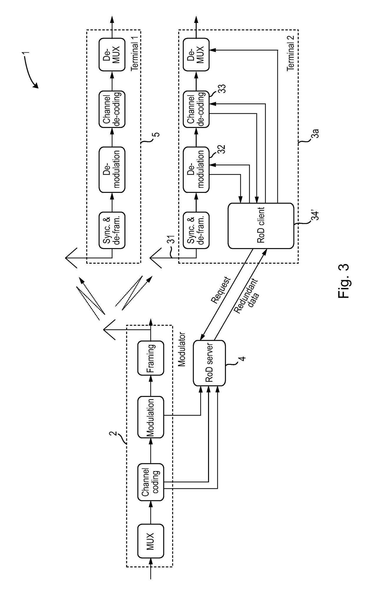
[0064]Referring now to the drawings, wherein like reference numerals designate identical or corresponding parts throughout the several views, FIG. 1 shows a schematic diagram of a broadcast system 1 according to the present disclosure. It comprises a broadcast transmitter 2 that transmits, via said broadcast system, a receiver input data stream comprising a plurality of channel symbols represented by constellation points in a constellation diagram. Further, it comprises one or more receivers 3, in this case two receivers indicated as “user A” and “user B” arranged at different distances from the broadcast transmitter 2, according to the present disclosure for receiving data transmitted by the broadcast transmitter 2. Still further, the broadcast system 1 comprises a broadband server 4 (also called broadband provider), in this case a redundancy server that provides redundancy data via a broadband system for reception by said receiver. Due to the use of transmission of data via broadc...


PUM


Abstract

A receiver for receiving data in a broadcast system includes a broadcast receiver that receives via the broadcast system a receiver input data stream including plural channel symbols represented by constellation points in a constellation diagram, a demodulator that demodulates the channel symbols into codewords, and a decoder that decodes the codewords into output data words. A redundancy calculator determines a required amount of redundancy data required for correct demodulation and decoding by use of the originally received channel symbol and additional redundancy data. A broadband request unit requests, if demodulation of a channel symbol and / or decoding of a codeword is erroneous or likely to fail, a required amount of redundancy data via a broadband system, that is received by a broadband receiver via said broadband system. The demodulator and / or the decoder is configured to use the redundancy data for demodulation and decoding, respectively.

Description

BACKGROUND[0001]Field of the Disclosure[0002]The present disclosure relates to receiver and a corresponding receiving method for receiving data in a broadcast system. Further, the present disclosure relates to a broadband server and a corresponding method for providing redundancy data and to a broadcast system.[0003]The present invention relates, for instance, to the field of Digital Video Broadcasting (DVB) utilizing Orthogonal Frequency Division Multiplexing (OFDM). Further, the present invention can be applied in other systems, such as a DAB (Digital Audio Broadcasting), DRM, MediaFlo, ISDB, ATSC (e.g. 3.0) or LTE broadcast system.[0004]Description of Related Art[0005]The transmission parameters of known broadcast systems, such as the broadcast systems in accordance with the DVB-T2 standard (second generation digital terrestrial television broadcast systems standard), are generally optimized for fixed reception with stationary receivers, e.g. with roof-top antennas. In future bro...

Claims


Application Information

Patent Timeline
Patent Type & Authority Patents(United States)
IPC IPC(8): H04B7/02H04L1/02H04L1/22H04L1/18H04L1/00H03M13/00H04L27/26
CPCH04L27/2649H03M13/6306H03M13/6552H04L1/007H04L1/0086H04L1/1819H04L1/1893H04L1/22H04H40/18H04L1/0046
Inventor QI, JUNGEROBERT, JOERGZOELLNER, JANSTADELMEIER, LOTHARLOGHIN, NABIL
Owner SATURN LICENSING LLC
Why Eureka
Try Eureka