Optical fiber for amplification and optical fiber amplifier using the same

a technology of optical fiber and amplifier, applied in the direction of cladded optical fiber, active medium materials, instruments, etc., can solve the problems of inconstant population inversion of erbium, uneven distribution of light pumping power, and need for more complicated optical systems, so as to reduce the difference in gains

Active Publication Date: 2017-07-04
THE FUJIKURA CABLE WORKS LTD +2
View PDF16 Cites 2 Cited by
  • Summary
  • Abstract
  • Description
  • Claims
  • Application Information

AI Technical Summary

Benefits of technology

[0008]Consequently, it is important to adjust the power of a light beam in each mode in pumping light propagating through the optical fiber for amplification, i.e., to adjust the excitation ratio of each mode in pumping light. However, since a complicated optical system is necessary to adjust the excitation ratio, a more complicated optical system is necessary as the number of modes is more increased. This creates demands that the number of modes of pumping light is decreased and the difference in gains between the LP01 mode and LP11 mode light beams in signal light beams is easily reduced.
[0009]Therefore, it is an object of the present invention is to provide an optical fiber for amplification and an optical fiber amplifier using the same that can easily reduce the difference in gains between the LP01 mode and LP11 mode light beams.
[0013]The relative refractive index difference of the inner core to the cladding is smaller than the relative refractive index difference of the outer core to the cladding. Thus, the power of the LP01 mode light beam can be unevenly distributed near to the outer core. Moreover, the outer core is doped with erbium. Consequently, in the case in which signal light beams propagate through the core, the difference in power between the LP01 mode and LP11 mode light beams propagating through the region of the core doped with erbium can be decreased. The theoretical cutoff wavelength of the LP02 mode light beam is a wavelength of 980 nm or less. Thus, in the case in which pumping light to pump erbium propagates through the core, the modes of the pumping light can be limited to the LP01 mode, the LP11 mode, the LP21 mode, and an LP31 mode. In Non Patent Literature 2 above, there are six modes for pumping light. Compared with this, the number of the modes of pumping light can be decreased. Consequently, the excitation ratio of light beams in these four modes only has to be controlled so that the gain of the LP01 mode light beam is equal to the gain of the LP11 mode light beam in signal light beams. Therefore, according to the optical fiber for amplification of the embodiment of the present invention, the difference in gains between the LP01 mode and LP11 mode light beams can be easily reduced.
[0019]In a region in which the ratio D1 / D2 is greater than 0.8, the difference between the sum total of the power of light in the LP01 mode signal light beam propagating through the outer core and the sum total of the power of light in the LP11 mode signal light beam propagating through the outer core is not greatly changed, compared with the difference in a region in which the ratio D1 / D2 is 0.8 or less. On the other hand, under the condition that the ratio D1 / D2 is 0.8 or less, decreases in the gains of the LP01 mode and LP11 mode light beams in signal light beams can be reduced.
[0023]This optical fiber amplifier can reduce the difference in gains between the LP01 mode and LP11 mode light beams in the C-band. Therefore, the optical fiber amplifier more appropriately allows few-mode communications in the C-band.
[0024]As described above, according to an aspect of the present invention, there are provided an optical fiber for amplification and an optical fiber amplifier using the same that can easily reduce the difference in gains between the LP01 mode and LP11 mode light beams.

Problems solved by technology

Thus, in the region doped with erbium in the core, the power of pumping light is unevenly distributed.
Consequently, in the region doped with erbium, the population inversion of erbium is inconstant.
However, since a complicated optical system is necessary to adjust the excitation ratio, a more complicated optical system is necessary as the number of modes is more increased.

Method used


Image

  • Optical fiber for amplification and optical fiber amplifier using the same
  • Optical fiber for amplification and optical fiber amplifier using the same
  • Optical fiber for amplification and optical fiber amplifier using the same

Examples


Embodiment Construction

[0041]In the following, a preferred embodiment of an optical fiber for amplification according to an embodiment of the present invention and an optical fiber amplifier using the same will be described in detail with reference to the drawings. For easy understanding, the scales of the drawings are sometimes different from the scales in the following description.

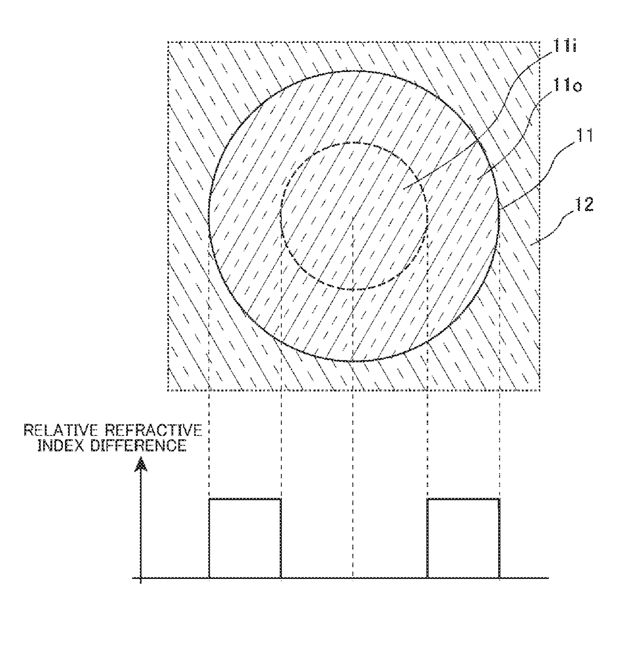
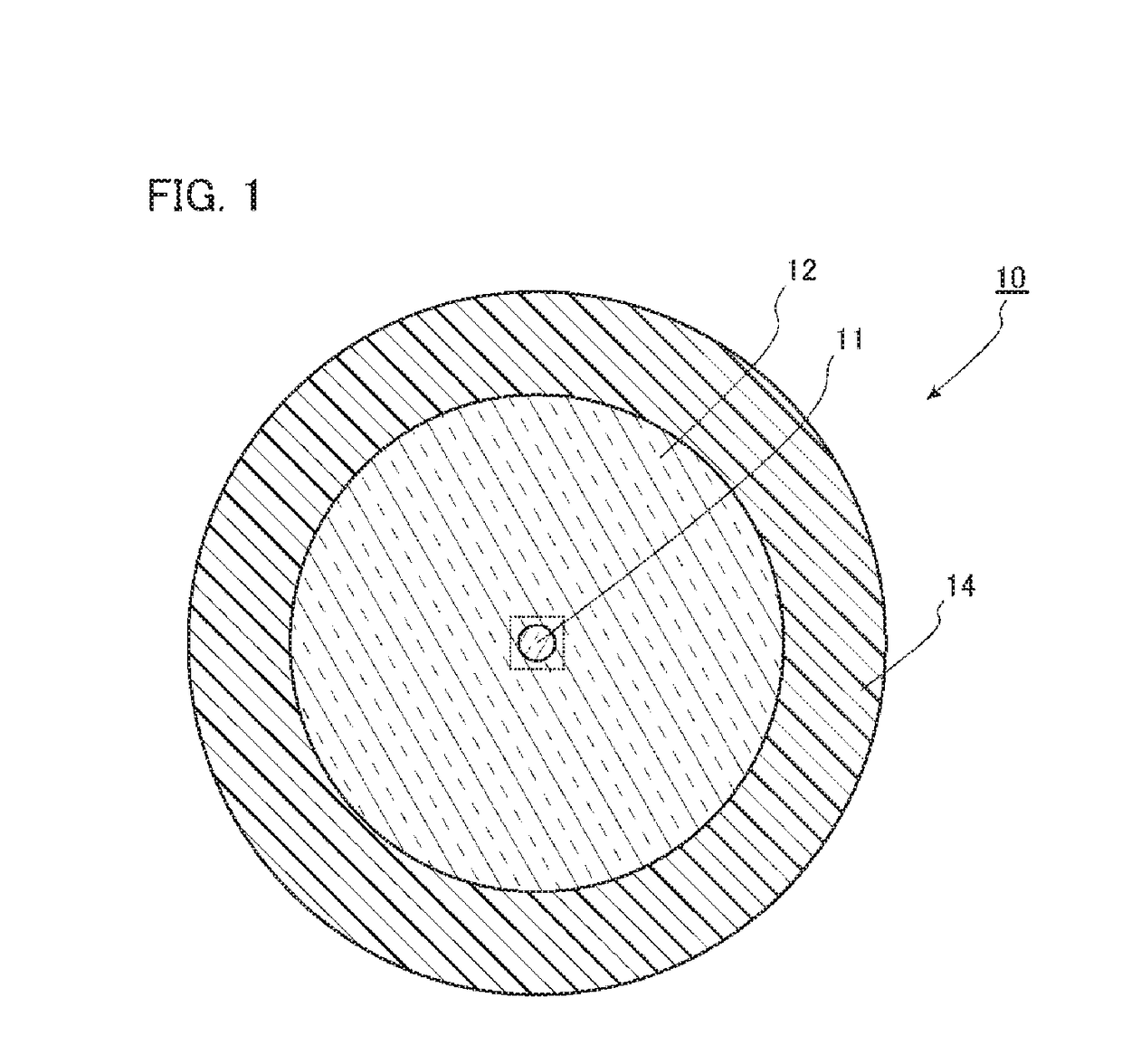
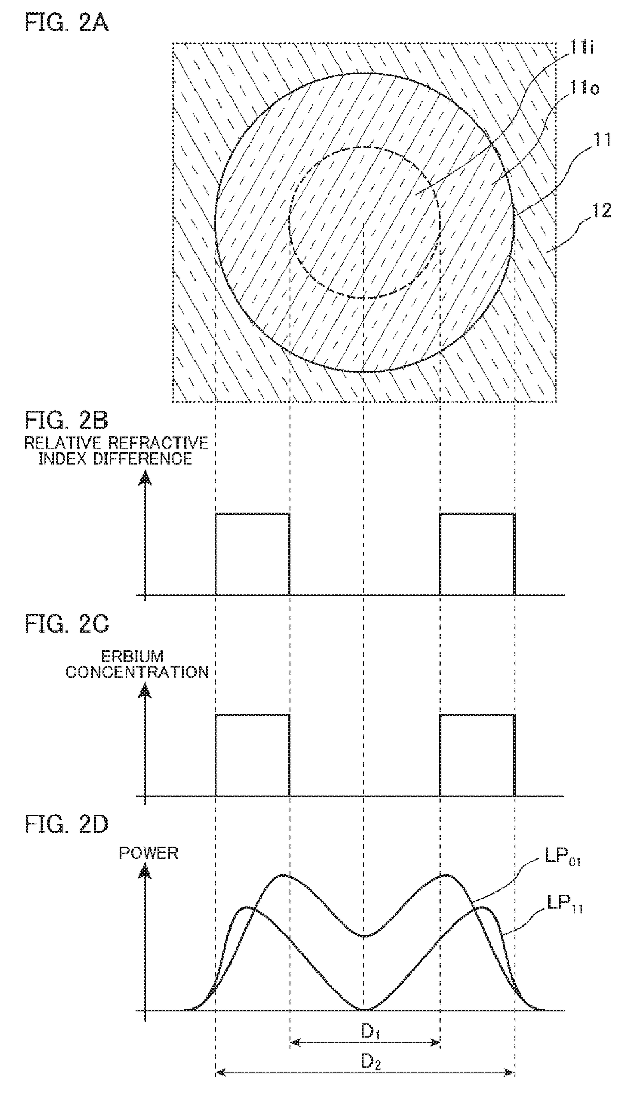
[0042]FIG. 1 is a diagram of a cross section perpendicular to the longitudinal direction of an optical fiber for amplification according to an embodiment of the present invention. As illustrated in FIG. 1, an optical fiber for amplification 10 includes a core 11, a cladding 12 surrounding the outer circumferential surface of the core 11 with no gap, and a buffer layer 14 covering the cladding 12 as main components. The diameter of the core 11 is 10 μm, for example. The outer diameter of the cladding 12 is 125 μm, for example.

[0043]The optical fiber for amplification 10 according to the embodiment is a few-mode fiber through wh...


PUM


Abstract

An optical fiber for amplification includes a core having an inner core and an outer core surrounding the outer circumferential surface of the inner core. The relative refractive index difference of the inner core to a cladding is smaller than the relative refractive index difference of the outer core to the cladding. The outer core is entirely doped with erbium. The theoretical cutoff wavelength of an LP11 mode light beam is a wavelength of 1,565 nm or more. The theoretical cutoff wavelength of an LP21 mode light beam is a wavelength of 1,530 nm or less. The theoretical cutoff wavelength of the LP02 mode light beam is a wavelength of 980 nm or less.

Description

BACKGROUND OF THE INVENTION[0001]The present invention relates to an optical fiber for amplification and an optical fiber amplifier using the same for use in optical communications, which are suitable for the case of reducing the difference in gains between an LP01 mode light beam and an LP11 mode light beam.[0002]In optical communications, signals are superposed on light beams propagating through an optical fiber for communications. In order to increase information volumes transmitted through a single core in such optical communications, there are known few-mode communications in which information is superposed on an LP01 mode (a fundamental mode) light beam and on an LP11 mode light beam of signal light beams for information communications. Therefore, in the case of amplifying signal light beams propagating through an optical fiber using an optical fiber amplifier, it is necessary to amplify both of the LP01 mode and LP02 mode light beams.[0003]Non Patent Literature 1 below descri...

Claims


Application Information

Patent Timeline
Patent Type & Authority Patents(United States)
IPC IPC(8): H01S3/067H01S3/094G02B6/036H01S3/16H01S3/08H01S3/0941
CPCH01S3/06729H01S3/06766H01S3/094069G02B6/03611H01S3/0804H01S3/09415H01S3/094003H01S3/1608
Inventor HOSOKAWA, TSUKASAICHII, KENTAROTAKENAGA, KATSUHIROMATSUO, SHOICHIROONO, HIROTAKAYAMADA, MAKOTO
Owner THE FUJIKURA CABLE WORKS LTD
Why Eureka
Try Eureka