Package structure including a cavity coupled to an injection gas channel composed of a permeable material

a permeable material and cavity technology, applied in the field of packaging, can solve the problems of difficult packaging and hermetically sealing cavities with very different residual pressures on the same substrate, difficult to achieve significant pressure differences between both cavities, and increase integration problems, etc., to achieve the effect of easy monitoring and higher pressure differences

Active Publication Date: 2017-07-11
COMMISSARIAT A LENERGIE ATOMIQUE ET AUX ENERGIES ALTERNATIVES
View PDF11 Cites 0 Cited by
  • Summary
  • Abstract
  • Description
  • Claims
  • Application Information

AI Technical Summary

Benefits of technology

[0019]There is thus a need to provide a packaging structure including at east one cavity the atmosphere of which can be easily monitored, which is compatible with the packaging of several micro-devices in different cavities at different pressures which are stable over time, and enabling, between the atmospheres of these cavities, higher pressure differences than with structures of prior art.
[0030]Depending on these different parameters, it is thus possible to achieve very different pressures in the cavity. Thus, such a packaging structure is perfectly compatible with making several closed cavities with atmospheres very different from each other, for example with pressure differences ranging from several bars to about 10−4 mbar.
[0031]Furthermore, the portion of the second non-permeable material enables a good sealing of the cavity to be ensured, especially when several cavities are made adjacent to each other and the layer of the first material is common to these different cavities.

Problems solved by technology

However, this type of integration raises problems.
But, it is very difficult to package and hermetically seal cavities with very different residual pressures on a same substrate.
This first solution is operational but does not enable significant pressure differences to be reached between both cavities: typically, the residual pressure in the cavity of the accelerometer is between a few mbars and a few tens mbars because of degassing of the different materials contained in the cavity of the accelerometer upon sealing.
In this case, this first solution is not operational.
However, because of the limited pumping capacity and the limited overall size of the getter material (the maximum size of which is limited by the dimensions of the cavity), it is generally not possible to get down to a residual pressure lower than about 1 mbar in the cavity of the gyrometer because the getter is saturated before reaching such a pressure.
However, such a structure does not enable pressure differences ranging from 1 bar to 10−3 mbar between the different cavities to be achieved.
Such a structure is however not suitable for making, on a same substrate, several cavities in which micro-devices are packaged under different atmospheres.
The drawback of this packaging structure is in particular that the pressure differences between the different cavities are very limited because of the permeable material communicating the different cavities between each other.
Furthermore, because of this permeable material present between the cavities, the gas tends, over time, to pass from one cavity to the other, and pressure values within the different cavities thus tend to change over time.

Method used


Image

  • Package structure including a cavity coupled to an injection gas channel composed of a permeable material
  • Package structure including a cavity coupled to an injection gas channel composed of a permeable material
  • Package structure including a cavity coupled to an injection gas channel composed of a permeable material

Examples


first embodiment

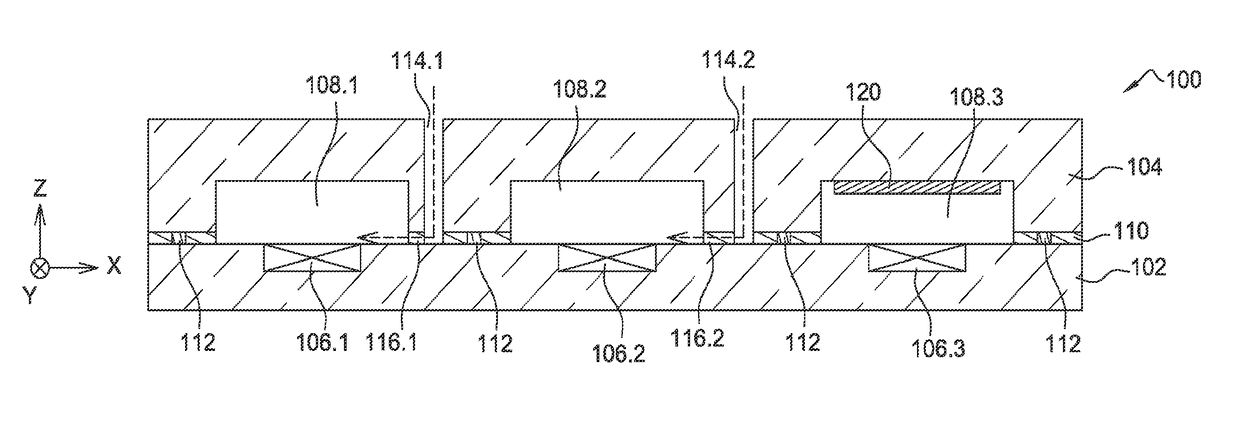
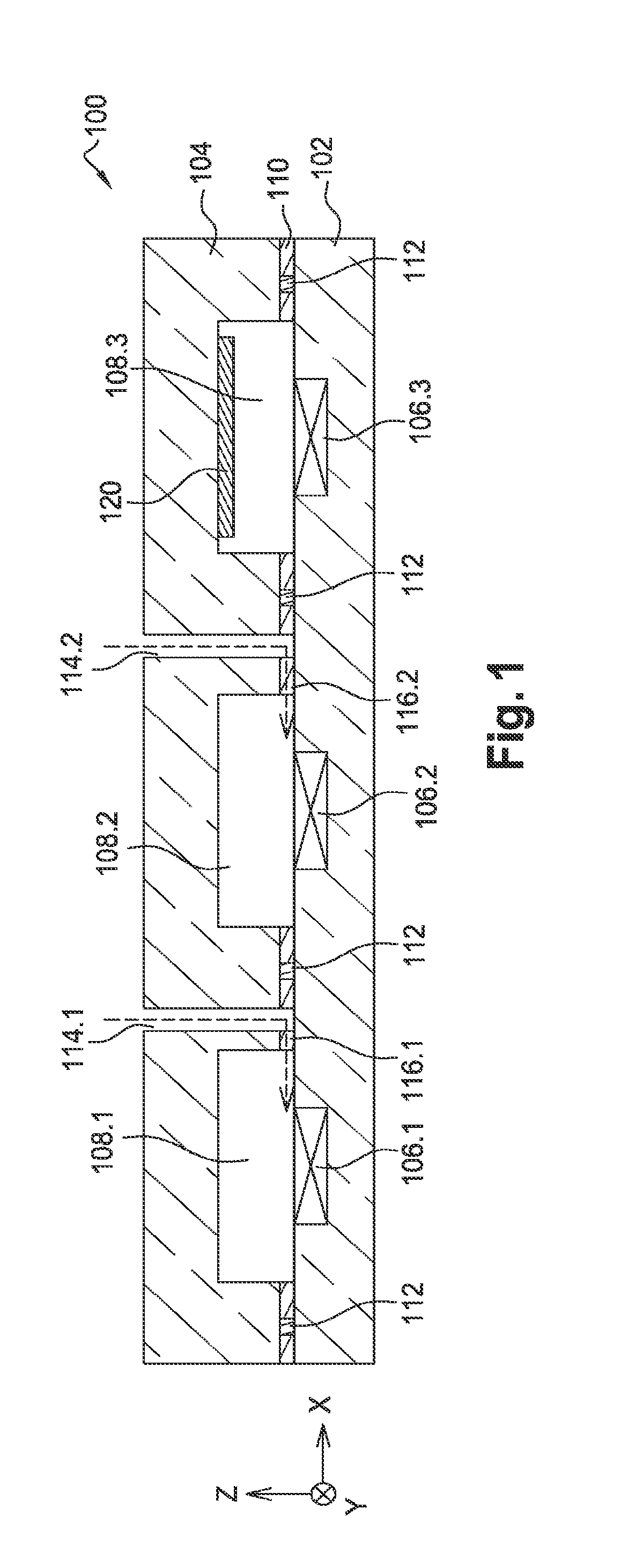
[0068]FIG. 1 is first referred to which shows a cross-section view of a profile of a packaging structure 100 according to a

[0069]The packaging structure 100 is herein formed by assembling a first substrate 102 with a second substrate 104. Both these substrates 102 and 104 each include a material non-permeable to a gas, advantageously a noble gas (corresponding to one type of noble gas or a mixture of different types of noble gases) to be injected in cavities of the structure 100, for example a semiconductor such as silicon.

[0070]One or more micro-devices 106 are made in and / or on the first substrate 102 which is used as a support for these micro-devices 106. In the example of FIG. 1, three micro-devices 106.1, 106.2 and 106.3 are made at a front face of the first substrate 102. The micro-devices 106 are each packaged in a cavity 108 (referenced 108.1, 108.2 and 108.3 in FIG. 1 respectively for each of the micro-devices 106.1, 106.2 and 106.3) formed between both substrates 102, 104....

second embodiment

[0101]A method for making the packaging structure 100 is described below in connection with FIGS. 6A to 6K.

[0102]This second embodiment differs from the first embodiment in that the gas is intended to be injected into the cavities through apertures and channels made in the first substrate including the micro-devices. As for previous FIGS. 5A to 5I, a single cavity 108 is shown in FIGS. 6A to 6K, even though the structure 100 may include several cavities 108 in which several micro-devices 106 are packaged.

[0103]In this second embodiment, the structure 100 is made from a first substrate 102 of the SOI (Silicon On Insulator)-type, or more generally of a semiconductor on insulator-type, including a solid layer 201, or support layer, the layer 110 arranged on the layer 201 and corresponding to the buried insulating layer (BOX) of the SOI substrate and the material of which (SiO2 for example) is permeable to the gas intended to be injected in the cavities of the packaging structure 100, ...


PUM

PropertyMeasurementUnit
Pressuresaaaaaaaaaa
Pressuresaaaaaaaaaa
pressureaaaaaaaaaa

Abstract

A packing structure including:a cap secured to at least one first substrate and forming at least one cavity between the cap and the first substrate;a layer of at least one first material permeable to a gas, arranged in the cap and / or in the first substrate and / or at the interface between the cap and the first substrate, and forming at least one part of a wall of the cavity;a portion of at least one second material non-permeable to said gas, the thickness of which is higher than or equal to that of the layer of the first material, and surrounding at least one first part of the layer of the first material forming said part of the wall of the cavity;an aperture passing through the cap or the first substrate and opening onto or into said part of the layer of the first material.

Description

TECHNICAL FIELD AND PRIOR ART[0001]The invention relates to the field of packaging, in particular for MEMS (micro-electro-mechanical systems), NEMS (nano-electro-mechanical systems), MOEMS (micro-opto-electro-mechanical systems), NOEMS (nano-opto-electro-mechanical systems)-type micro-devices, or also pressure sensors, in hermetic cavities and under particular atmospheres.[0002]The packaging of a micro-device in a cavity enables it on the one hand to be protected against external elements (humidity, particulate pollution, reactive elements such as oxygen or other non-neutral gases), and on the other hand, the atmosphere in which the micro-device is packaged to be controlled, both in terms of pressure and gas composition.[0003]Pressures with which the micro-devices are packaged are very variable depending on their application and are typically between about 1 bar and 10−3 mbar. A recurrent requirement during such a packaging is thus to make a very accurate monitoring of the pressure ...

Claims


Application Information

Patent Timeline
Patent Type & Authority Patents(United States)
IPC IPC(8): B81B7/00B81C1/00
CPCB81B7/0038B81C1/00285B81B2201/0235B81B2201/0242B81B2207/097B81C2203/0109B81C2203/0118B81C2203/0145H01L2224/11
Inventor NICOLAS, STEPHANE
Owner COMMISSARIAT A LENERGIE ATOMIQUE ET AUX ENERGIES ALTERNATIVES
Why Eureka
Try Eureka