
Boiler for domestic appliances and water heating systems with steam production for home and industrial use

a technology for domestic appliances and water heating systems, applied in the direction of heating types, lighting and heating apparatus, applications, etc., can solve the problems of inability to achieve high efficiency, disadvantageous ratio of the total length of the radiant surface of the resistor to the volume of water to be heated, and inconvenient use, so as to reduce the size of the boiler and its water capacity, avoid the loss of parts of thermal energy, and achieve high and substantially consistent steam production

Active Publication Date: 2017-07-11
T P A IMPEX
View PDF67 Cites 6 Cited by
  • Summary
  • Abstract
  • Description
  • Claims
  • Application Information

AI Technical Summary

Benefits of technology

This configuration improves steam production efficiency, reduces boiler size and weight, and ensures continuous steam supply without lengthy heating cycles, while minimizing power loss and extending resistor lifespan.

Problems solved by technology

These resistors usually have a rectilinear and substantially elongate shape, to be almost entirely immersed in the volume of water to be heated while occupying as small a space as possible, such that the boilers also have small dimensions, and do not increase the overall size of the appliances in which they are placed.
This prior art suffers from certain drawbacks.
A first drawback is that, in prior art boilers, the ratio of the total length of the radiant surface of the resistors to the volume of water to be heated is disadvantageous and does not afford high efficiency.
A further drawback is that this kind of linear resistors have a limited length, whereby the power supply exceeds the limits of the resistor surface area, which involves a risk of melting or failure of the resistors.
Furthermore, no quick and substantially smooth steam production can be obtained, namely because the radiant surface of the heating resistors is very small as compared with the boiler size, whereby heating and steam production times are long and discontinuous.
Another drawback is that heat exchange between the radiant surfaces of the electric resistors and the water to be heated occurs by simple direct contact therebetween, and no particular arrangement is provided for enhancing the heating effect of resistors or, assuming a target heating temperature, for reducing the power supply required to attain a target temperature and cause boiler water to evaporate and produce steam.
A further drawback is that, when the pressure safety valve cuts off power to the electric resistor as a predetermined pressure limit is reached in the heating chamber of the boiler due to steam generation, a considerable amount of the steam so produced shall be emptied for the pressure safety valve to restore power to the resistor, and hence start a new water heating cycle.
This adversely affects the overall efficiency of the domestic appliances with steam production because, while the boiler is being emptied of the steam by ejection thereof, with the resistor being powered off, a volume of cold refilling water is automatically introduced into the boiler, such cold water mixing with the water therein that has been heated by a previous heating cycle and is still in the heating chamber.
Therefore, the overall water temperature is decreased and parts of the power supplied to the resistor for heating are cyclically lost, which will increase the temperature drop that will be covered by the resistor, by heating again the water in the heating chamber once the pressure safety valve restores power for a subsequent heating and steam production step.
Another drawback is that prior art boilers have a large size and require accordingly large housings in the domestic appliances, whose design is affected by this requirement, with designers being limited in their ability to provide domestic appliances with steam production having a more pleasant appearance, improved ergonomic features, a lighter weight and easier storage even in small spaces, when not in use.

Method used


Image

  • Boiler for domestic appliances and water heating systems with steam production for home and industrial use
  • Boiler for domestic appliances and water heating systems with steam production for home and industrial use
  • Boiler for domestic appliances and water heating systems with steam production for home and industrial use

Examples


Embodiment Construction

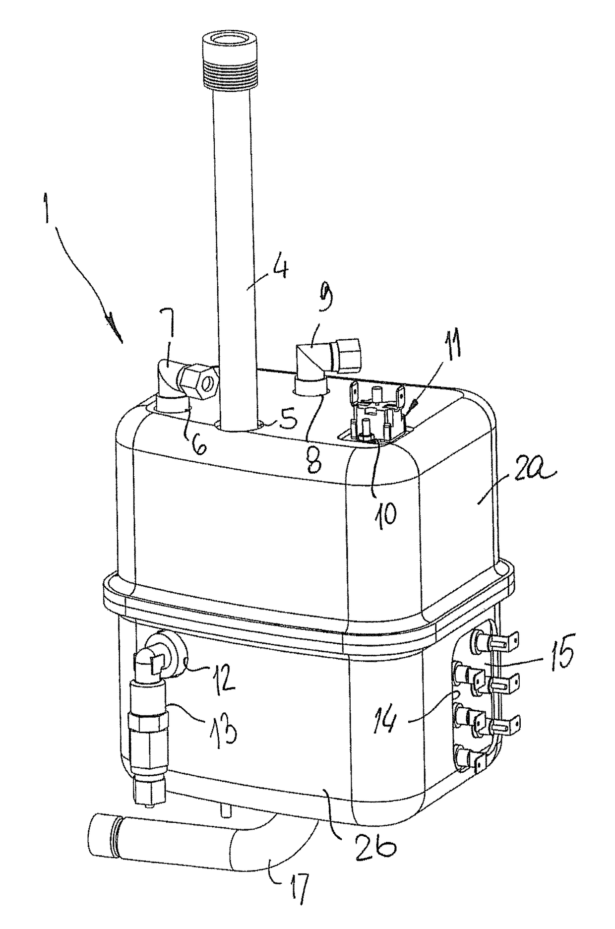
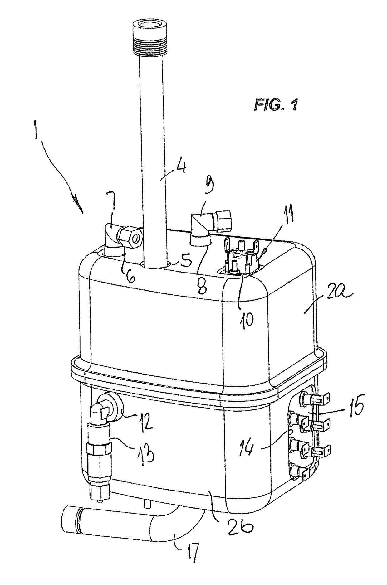
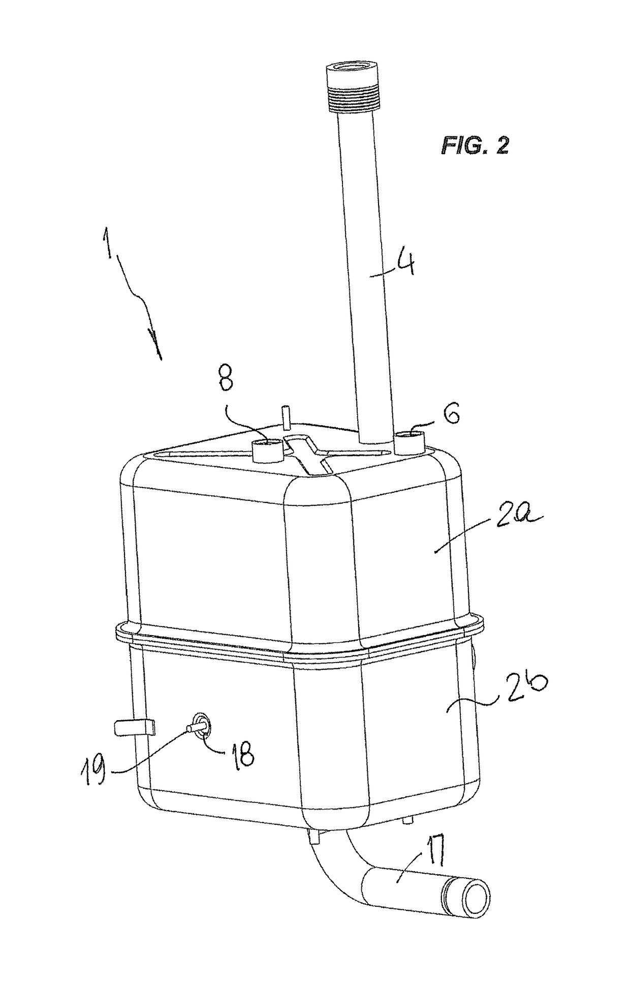
[0038]Referring to the accompanying figures, numeral 1 generally designates a boiler for domestic appliances and water heating systems with steam production for home and industrial use.

[0039]The boiler 1 comprises a box-like container body, which is composed of upper and lower half-shells 2a, 2b, stably joined together by joining means, e.g. by welding, and defining therein a fluid-tight heating chamber 3, which is designed to contain a liquid to be heated and vaporized, namely water.

[0040]The box-like body of the boiler 1 is equipped with a plurality of apertures that are designed to receive elements mounted thereto for operating a domestic appliance with steam production, namely a cleaning appliance, with the boiler 1 being adapted to be mounted thereto.

[0041]Namely, the upper half-shell 2a is formed with an aperture 5 for connection of a union 4 for filling the heating camber 3 with a predetermined volume of water or introducing a water level probe, an aperture 6 for connection o...


PUM


Abstract

A boiler for domestic appliances and water heating systems with steam production for home and industrial use includes: a container body configured to contain a liquid to be heated and vaporized, and defining an inner containment chamber having a containment volume; a heating device having a radiant heating surface, the heating device including at least one pair of radiant elements having respective radiant surfaces accommodated in the containment chamber, in parallel and spaced relationship, and designed to be immersed in the liquid to cause a convective motion of the liquid between the radiant surfaces.

Description

FIELD OF THE INVENTION[0001]The invention relates to a boiler for domestic appliances and water heating systems with steam production for home and industrial use, which is generally intended for steam production in cleaning and disinfection appliances.BACKGROUND ART[0002]Domestic appliances have been long known and used, which are equipped with steam production devices emitting jets for cleaning and disinfecting wall or furniture surfaces.[0003]Particularly, these domestic appliances comprise a boiler which is filled with water and in which an electric resistor is immersed, which resistor is supplied with power and heats up, thereby heating water by conduction to an evaporation or heating temperature with hot water production.[0004]A volume of steam is generated in the boiler, at a pressure higher than atmospheric pressure, which is controlled by a pressure safety valve or a similar device, that switches off the electric resistor each time that pressure reaches a maximum preset limi...

Claims


Application Information

Patent Timeline
Patent Type & Authority Patents(United States)
IPC IPC(8): A61M16/00F24F3/14F22B1/28
CPCF22B1/28F22B1/284
Inventor AMORETTI, LUIGI
Owner T P A IMPEX
Learn More