
Method and apparatus for testing of engine components

a technology for engine components and testing methods, applied in the direction of machines/engines, fluorescence/phosphorescence, instruments, etc., can solve the problems of significant mechanical and safety risks, use of alm methods, and difficulty in servicing, maintenance and/or repair procedures, so as to facilitate the flow or permit the flow, minimise or eliminate any risk, and enhance the effect of optical contras

Active Publication Date: 2017-07-11
ROLLS ROYCE PLC
View PDF10 Cites 4 Cited by
  • Summary
  • Abstract
  • Description
  • Claims
  • Application Information

AI Technical Summary

Benefits of technology

[0024]Embodiments of the present invention exploit the phenomenon of scattering of electromagnetic radiation by an “active” material which is able to scatter electromagnetic radiation, in order to provide a comparative map of scattered and non-scattered radiation in or entering the second region to the second side of the component wall, or portion thereof, being tested. By detecting any scattered radiation in that second region, the presence, location and / or intensity of which is indicative of material having passed through one or more substantially unblocked through-holes in the wall portion from the first to the second side, and then comparing that detected scattering pattern with the general known pattern of through-holes in the portion of the wall under test, it is possible to readily determine the existence and / or location and / or identity of any through-holes in the wall portion which are blocked or partially blocked.
[0028]In various embodiments, and preferably depending at least partly on the identity of the active scattering material used, the active scattering material may be provided in the form of particles of a solid material or as particles or droplets of a liquid material. Either form of particles may in some embodiments be provided as dispersed (or possibly even dissolved) particles or micro-particles in a carrier medium, especially a fluid carrier medium, whereby the above-defined test fluid may in some embodiments comprise the said carrier medium with the said particles of active material dispersed (or possibly even dissolved) therein. The carrier medium may be a liquid or, more preferably, a gas, e.g. air. A gaseous carrier medium may in some embodiments be particularly preferred, as it may be more easily provided as a supply thereof and may be easier to be caused or permitted to flow from the first region to the second region by natural convection or pumping.
[0029]Thus, is some embodiments of the invention the test fluid may conveniently comprise a colloidal dispersion, suspension or solution of the active scattering material, in the form of solid or liquid particles, in a fluid, especially a gaseous, carrier medium. Accordingly, in some embodiments of the invention, where the active scattering material is in the form of particles (solid or liquid), the particles may typically for example have an average particle size in the range of from about 1 nm to about 1 μm. Optionally, particle sizes of the active material in excess of 1 μm, e.g. up to about 5 or 10 or 20 or 50 or even 100 μm, or possibly even greater, may in certain cases be used, if the carrier medium and active material are selected accordingly so that the test fluid is a stable composition and its components remain in their respective physical states without settling, precipitation or separation during the testing method. Generally it is preferred to use particle sizes of the active material which are significantly smaller than the minimum diameter of the through-holes of the component wall, or portion thereof, under test, in order to minimise or eliminate any risk of the test fluid itself blocking the holes during the test procedure.
[0030]Suitable active scattering materials for use in embodiments of the invention may include for example solid micro-particles of titanium dioxide (TiO2), flakes of aluminium (Al) metal, or a suitable smoke material. Gaseous dispersions of various radiation-scattering oils may also be used as the active scattering material. Examples of suitable light-scattering oils may include olive oil, vegetable oils, odena oil. Another example of a suitable light-scattering material is water, especially in the form of water droplets or vapour, e.g. in the form of dry-ice-condensed water vapour. Yet another example of a suitable light-scattering material is micro-particles or micro-spheres of glass or a glass material, which materials may often suitably be employed in the form of a dispersion thereof in a liquid carrier medium. Optionally, particles of one or more coloured light-scattering materials and / or fluorescent materials may be used as the, or as a component of the, active scattering material, in order to provide enhanced optical contrast in the detection of light-scattering flows and / or to assist in discriminating between detected scattered signals and the relevant background.
[0044]Such a temporary blocking, e.g. by simple application of a removable occluding or fluid-impervious tape or shield element, of the through-hole(s) in any portion of the component wall not being tested, may thus serve to avoid any misreadings or rogue data obtained by inadvertent passage of test fluid through wall(s) or wall portions of the component which are not under test.

Problems solved by technology

The use of such small through-holes for film cooling can present difficulties in servicing, maintenance and / or repair procedures, as it is often necessary to be able to detect whether any—or any appreciable number—of the holes are blocked, e.g. as a result of the presence or build-up of combustion or other deposits such as dirt, pollution or environmental residues during extended use of the engine, or even as a result of remnant material left over from the manufacture of the component itself.
Hole blockages can pose significant mechanical and safety risks, since a hole that is blocked cannot pass therethrough a required flow of cooling fluid, which may result—especially if several or many holes are blocked simultaneously—in the component overheating, or even ultimately prematurely failing.
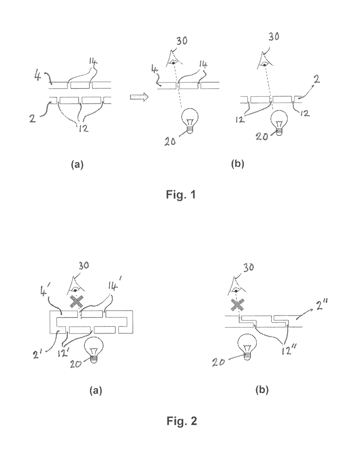
However, the use of ALM methods comes with new disadvantages with respect to being able to inspect such components for potential blockage of through-holes in the walls thereof using a conventional line-of-sight inspection technique using visible light as discussed above.
This is because although ALM manufacturing tolerances allow accurate relative positioning between e.g. impingement and effusion holes, this is only possible by building both hot and cold walls of a multi-walled component as a single integrated piece, and in that case through-holes in each respective wall may often not be in alignment such as to permit use of the above line-of-sight inspection technique.
Furthermore ALM methods also allow complex, non-straight through-hole shapes to be manufactured, which can be useful to employ in practice but which again may prevent the use of the above line-of-sight inspection technique because of the absence of a direct straight line light path through such a non-straight hole configuration.
Moreover, in the case of unitary multi-walled components which define a void between a pair of walls, e.g. spaced apart “hot” and “cold” walls formed in a single piece with each wall containing its own arrangement of through-holes (perhaps even straight holes), the mere presence of the void may also often prevent use of the above line-of-sight inspection technique, since through-holes of the respective sets in the facing walls may often be arranged with their longitudinal axes non-coincident, in which case it is impossible for light to pass through both sets of holes simultaneously even if both holes of a given pair in the two walls are clear / unblocked.
Thus, in many modern manufacturing techniques for engine components comprising various arrangements and configurations of one or more through-holes in at least one wall thereof, conventional line-of sight inspection techniques are impossible to use.
Such known systems are generally complex, expensive and slow to implement on a large industrial scale, and they also fail to address at least some of the specific problems associated with modern component manufacturing methods, such as ALM, as discussed above.

Method used


Image

  • Method and apparatus for testing of engine components
  • Method and apparatus for testing of engine components
  • Method and apparatus for testing of engine components

Examples


Embodiment Construction

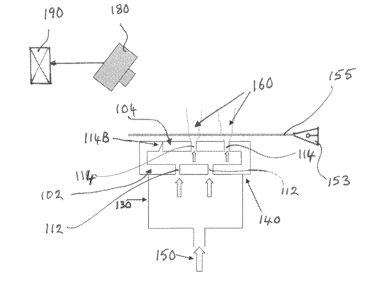
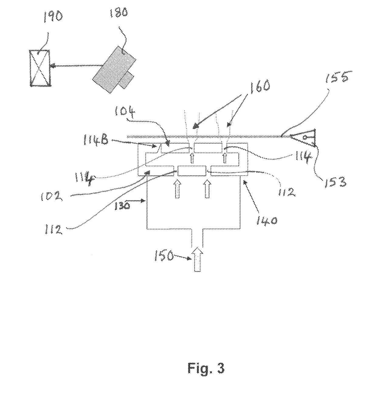
[0059]Referring to FIG. 3 of the drawings (FIGS. 1 and 2 having already been referred to in the context of the prior art), here there is shown schematically a test arrangement in accordance with an embodiment of the invention. For the most part this illustration will be self-explanatory, in view of the foregoing description and discussion.

[0060]As shown in FIG. 3, the engine component comprises a pair of walls 102, 104, which are shown here by way of example as being twin wall sections of a unitarily formed integrated piece, such as that formed by an additive layer deposition (ALM) method. The wall 102 comprises a plurality of through-holes 112 therein, which may be of any number and in any pattern, and the wall 104 likewise comprises a plurality of through-holes 114 therein, again in any number and pattern. In this illustrated example, it is the wall 104 which is to be tested for the occurrence and / or location and / or identity of one or more of the through-holes 114 therein which ma...


PUM


Abstract

Method and apparatus testing engine component, for blockage of one or more through-holes in a portion of a wall. The method including (i) providing a supply of test fluid, (ii) causing or permitting flow of test fluid to occur from first to second region, (iii) illuminating the second region with electromagnetic radiation to cause scattering of electromagnetic radiation by material exiting substantially non-blocked through-holes in wall portion having passed therethrough from the first to second side, (iv) detecting said scattering of electromagnetic radiation from said substantially non-blocked through-holes; and (v) comparing said detected scattering of electromagnetic radiation from said substantially non-blocked holes with known pattern of through-holes in component wall portion to determine the presence and / or location and / or identity of any blocked or partially blocked through-holes in component wall portion.

Description

TECHNICAL FIELD[0001]This invention relates to the testing of engine components, especially components of gas turbine engines, and to a method and apparatus for so doing. More particularly, though not exclusively, the invention relates to the testing of engine components which comprise one or more holes, often a large number of holes, e.g. for cooling purposes, to determine if any of such holes are blocked.BACKGROUND OF THE INVENTION AND PRIOR ART[0002]Various components in gas turbine engines utilise arrangements of through-holes in their walls for the purpose of establishing various kinds and configurations of cooling arrangements therein. Such components may include for example combustor cassettes, combustion chamber heat shields and barrels, turbine blades, guide vanes, exhaust ducts and so on, and they are often manufactured by conventional investment casting techniques. Typically such components include small, substantially straight through-holes, often a plurality or even a l...

Claims


Application Information

Patent Timeline
Patent Type & Authority Patents(United States)
IPC IPC(8): G01N21/00G01N21/53G01M15/14G01N21/64F01D21/00G01N21/956F01D5/18
CPCG01N21/53F01D5/186F01D21/003G01M15/14G01N21/64G01N21/95692B23P2700/06F05D2260/202F05D2260/607F05D2260/83G01N2201/023
Inventor WORTH, NICHOLAS AHARDING, STEPHEN C.
Owner ROLLS ROYCE PLC
Learn More