System and method for machining a workpiece

a technology for machining systems and workpieces, applied in the direction of turning apparatuses, milling equipments, large fixed members, etc., can solve the problems of ever more difficult to develop appropriate materials for tools, and achieve the effect of short time, optimal tool deployment, and positive effect on tough materials

Active Publication Date: 2017-07-18
EV GRP E THALLNER GMBH
View PDF18 Cites 1 Cited by
  • Summary
  • Abstract
  • Description
  • Claims
  • Application Information

AI Technical Summary

Benefits of technology

The tool achieves reduced wear, increased service life, and higher machining speed, effectively handling materials with Knoop hardness above 1, particularly those like cubic boron nitride and diamond, with efficient chip removal and minimal tool loading.

Problems solved by technology

In particular in the case of high-strength materials, such as carbide and nitride ceramics, it is ever more difficult to develop appropriate materials for the tools that are to be used for machining, since these must possess a very high hardness, strength and, above all, also toughness.

Method used


Image

  • System and method for machining a workpiece
  • System and method for machining a workpiece
  • System and method for machining a workpiece

Examples


Embodiment Construction

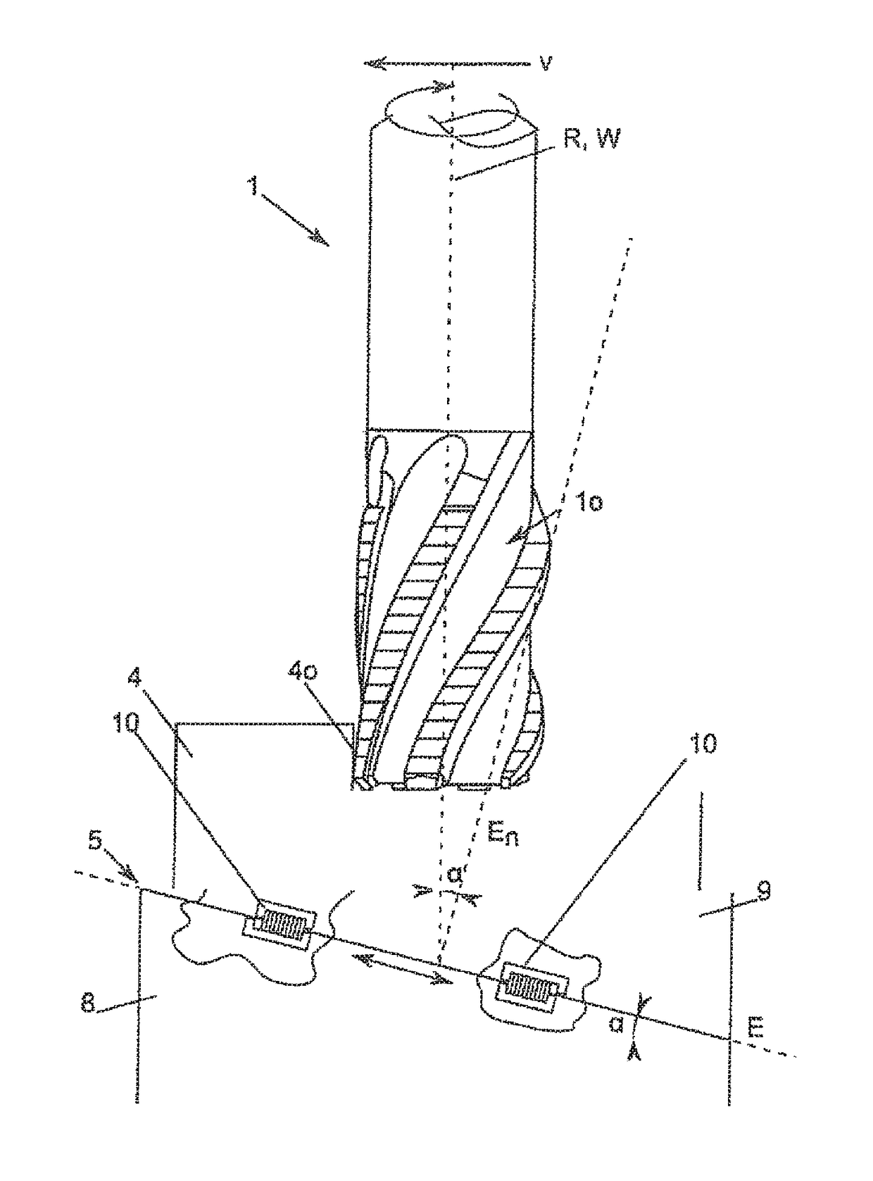
[0131]FIG. 1 shows a schematically represented tool 1, not to scale, (here a roughing milling cutter) with a tool surface 1o. The tool experiences a feed in a feed direction v, and in the particular form of embodiment rotates about an axis of rotation R / tool longitudinal axis W. From the direction of rotation a cutting direction s ensues along a workpiece surface 4o of a workpiece 4 that is being machined.

[0132]The tool surface 1o of the tool 1 contacts the workpiece 4 on the workpiece surface 4o. The workpiece 4 is mounted / fixed on a workpiece holder 5. With regard to the workpiece holder 5 reference is made to W02012 / 084779A1. The workpiece holder 5 is constructed such that it can allow the workpiece 4 to oscillate along a plane E; the vector En normal to the plane possesses an angle of inclination α to the tool longitudinal axis W, and / or is inclined relative to the feed direction v and / or the cutting direction s.

[0133]To this end the workpiece holder 5 is comprised of a first os...


PUM

PropertyMeasurementUnit
sizeaaaaaaaaaa
breaking stressesaaaaaaaaaa

Abstract

A workpiece accommodation device for purposes of accommodating a workpiece and for use in a device for the machining of a workpiece with: a tool mounting for purposes of accommodating the tool, a workpiece accommodation device for purposes of accommodating the workpiece, characterized in that during the machining process at least one first oscillation component can be introduced in a Z-direction, and an, in particular simultaneous, second oscillation component can be introduced in an X- and / or Y-direction by means of oscillation components.

Description

FIELD OF INVENTION[0001]The present invention concerns a system for machining a workpiece, and a corresponding method.BACKGROUND OF INVENTION[0002]At the present day semi-finished products can be machined using various production technologies in a short period of time with very tight tolerances. The progress in the chip-forming and chip-less machining of workpieces can primarily be attributed to the rapid progress made in tool technology and machine tool technology. A machine tool is understood to be a machine that accommodates the tool and guides the latter relative to a workpiece. The tool is the component that is directly positioned against the workpiece that is being machined, in order to machine the latter. A multiplicity of different tools exist for various machine tools, for example, drill bits, milling cutters, grinding wheels, wires, chisels, thread cutters, etc.[0003]The application of these tools ensues predominantly from their area of deployment. This will be illustrated...

Claims


Application Information

Patent Timeline
Patent Type & AuthorityPatents(United States)
IPC IPC(8): B23Q1/34B23C5/16B23B51/00
CPCB23Q1/34B23B51/00B23C5/16B23B2226/31B23B2228/56B23C2210/03B23C2222/28B23C2226/31B23C2270/10Y10T409/305488Y10T409/307448B23C2220/48
InventorTIEFENBOCK, HERBERT
OwnerEV GRP E THALLNER GMBH