Saw blade with tooth form projection

a technology of tooth-forming projection and saw blade, which is applied in the direction of band saws, saw chains, manufacturing tools, etc., can solve the problems of blade wear, rapid tool wear, and inability to cut materials as straight as desired, so as to reduce the tool/chip contact zone, reduce the heat generation, and maximize the use of available tooth-gullet capacity

Active Publication Date: 2017-08-15
BLACK & DECKER INC
View PDF107 Cites 8 Cited by
  • Summary
  • Abstract
  • Description
  • Claims
  • Application Information

AI Technical Summary

Benefits of technology

[0014]One advantage of the present invention is that the substantially flat, linear, or non-curvilinear projection or like means allows for the creation of relatively tightly curled metal chips that are projected or moved away from the front edge or rake face of the tooth toward the far or opposite side of the gullet. This redirecting of the forming chip results in an efficient use of available tooth gullet capacity and a reduction in the heat generated at the rake face surface due to the minimized tool / chip contact zone in comparison to prior art metal cutting saw blades. Yet another advantage of the currently preferred embodiments of the present invention is that the depth of the projection, and the length and inclined angle of the projection, are within a geometry window that facilitates formation of relatively tightly curled metal chips without the adverse effects of increased cutting forces at the tooth tip as encountered in prior art saw blades. More specifically, because the substantially flat, linear, or non-curvilinear projection is located at a depth below the tooth tip within the range of about 25 / 1000 inch to about 65 / 1000 inch, and preferably within the range of about 30 / 1000 inch to about 55 / 1000 inch, and because the distance between the inner end and the outer end of the projection in a direction substantially parallel to the plane extending between the tips of at least two teeth is within the range of about 5 / 1000 inch to about 25 / 1000 inch, and more preferably within the range of about 8 / 1000 inch to about 20 / 1000 inch, the projection is allowed to form relatively tightly curled metal chips substantially without the adverse effects of increased cutting forces at the tooth tip. Yet another advantage is that the substantially flat, linear, or non-curvilinear projection tangentially contacts the chips to minimize the surface area of the projection in contact with the chips and the resulting cutting forces imparted on the tooth, while nevertheless forming relatively tightly curled chips and projecting or moving them toward the opposite side of the gullet.
[0015]Yet another advantage of some currently preferred embodiments of the present invention is that they incorporate multi-level set geometries for both increasing blade life and providing straighter cuts in comparison to prior art saw blades. It has been discovered that a primary driver for overall cutting forces is the relative cutting efficiency of the unset and relatively light set teeth. Accordingly, in the currently preferred embodiments of the present invention, these teeth define relatively aggressive rake angles along with the chip-controlling projection described above to penetrate the sawn material with a relatively low resistance. It also has been discovered that a key to relatively long blade life with relatively straight cuts resides in the relatively heavy set teeth. In some embodiments of the present invention, the relatively heavy set teeth define less aggressive rake angles, preferably within the range of about 60% to about 80% of the rake angles of the unset and relatively light set teeth. The relatively less aggressive rake angles allow the heavy set teeth to maintain substantially straight cuts due to the relatively slow or controlled wear of such teeth, while nevertheless maintaining relatively low cutting forces and tightly controlled chips due to the geometries of the unset and light set teeth, as described above.
[0016]Yet another advantage of some embodiments of the present invention is that the heavy set teeth define relatively shallow primary clearance angles in comparison to the unset and relatively light set teeth, such as clearance angles within the range of about 0° to about 8°, and define primary clearance surface lengths within the range of about 2 / 1000 inch to about 6 / 1000 inch, to thereby impart a relatively stable, “pre-worn” tooth geometry to the relatively heavy set teeth. As a result, the relatively heavy set teeth wear in a relatively even or consistent manner by avoiding the relatively chaotic tooth wear that can be inherent in saw teeth with sharper tips (e.g., with more aggressive primary clearance angles and / or longer primary clearance surfaces), while nevertheless maintaining relatively low cutting forces and tightly controlled chips due to the geometries of the unset and light set teeth, as described above.
[0017]Accordingly, the saw blades of the present invention, such as metal-cutting band saw blades, provide significant user benefits when cutting difficult-to-cut materials, such as tool steels, stainless steels, nickel-based alloys, or other hardened or work hardened materials and / or materials that exhibit relatively high shear stress. Yet another advantage of the saw blades of the present invention is that they allow such materials to be cut with increased blade life and straighter cuts in comparison to prior art saw blades.

Problems solved by technology

One of the drawbacks of prior art band saw blades, particularly band saw blades that are used to cut difficult-to-cut materials, such as tool steels, stainless steels, nickel-based alloys, or other hardened or work hardened materials and / or materials that exhibit relatively high shear stress, is that the blade life is not as long as desired and / or the blades do not cut the materials as straight as desired.
Although these methodologies can be moderately effective when the blades are new, and therefore relatively sharp, they have significant drawbacks.
The first methodology leads to rapid tool wear due to the use of relatively aggressive, “self-feeding” geometries on the rake faces of kerf-generating teeth.
This approach tends to fracture or “chip-out” these teeth in an uncontrolled, unpredictable manner.
With the second methodology, on the other hand, the full-contact radius feature allows for an extended tool-chip interface region that leads to increased cutting forces and higher heat generation back into the tool which, in turn, leads to more rapid wear than desired.

Method used


Image

  • Saw blade with tooth form projection
  • Saw blade with tooth form projection
  • Saw blade with tooth form projection

Examples


Embodiment Construction

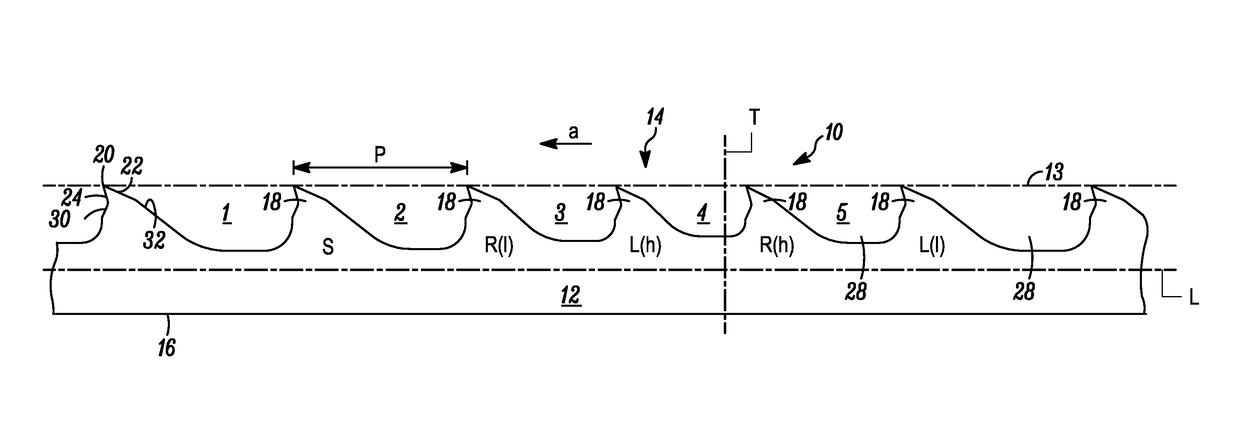
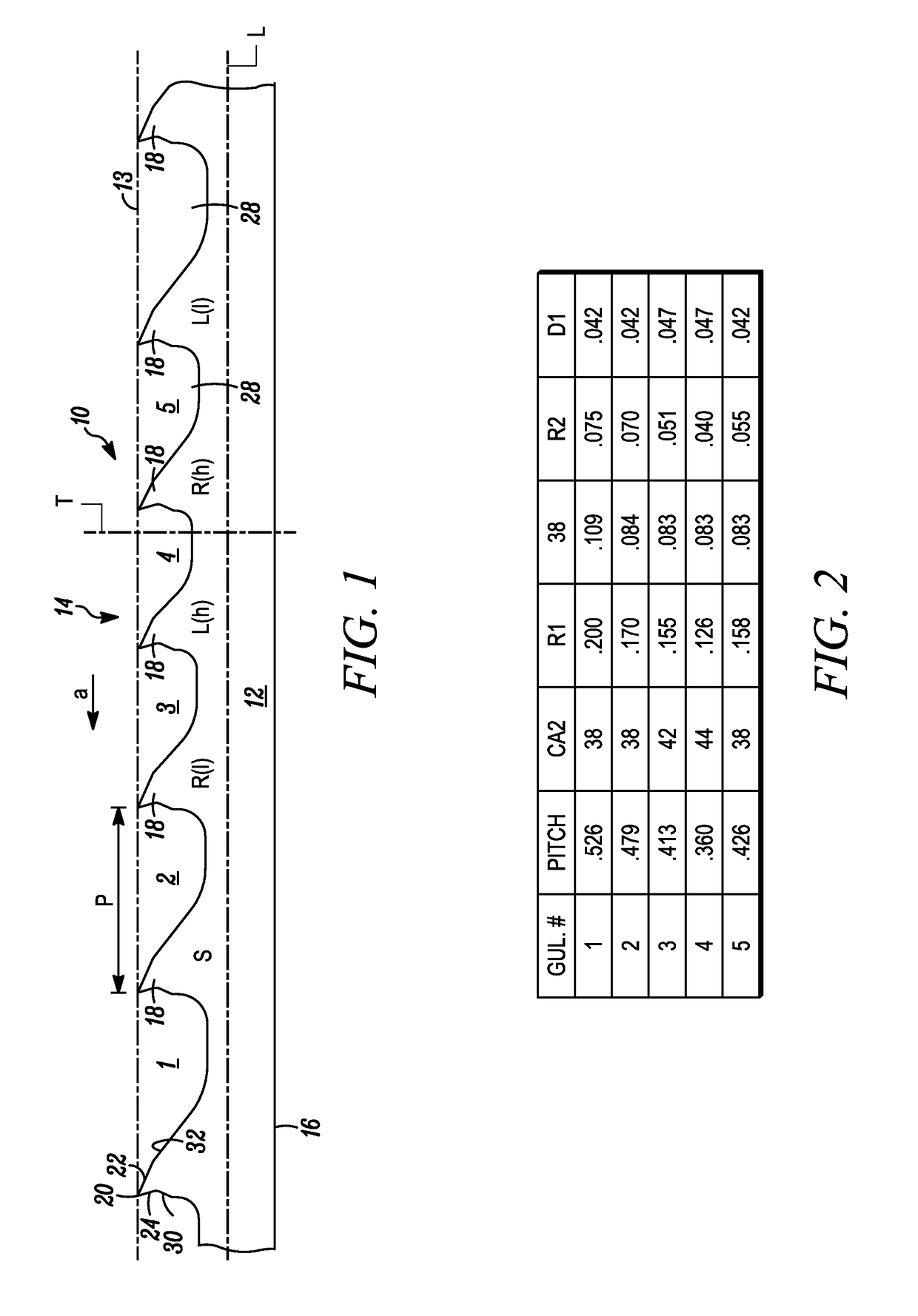
[0024]In FIG. 1, a saw blade for cutting difficult-to-cut materials in accordance with an embodiment of the present invention is indicated generally by the reference numeral 10. In FIG. 1, the saw blade 10 is a band saw blade comprising a band 12 having a cutting edge 14 and a back edge 16, and defining a longitudinal axis “L” and a transverse axis “T”. The direction of cutting (the forward direction) is indicated by the arrow “a”. The cutting edge 14 of the band saw blade 10 includes a plurality of teeth 18, 18 thereon. The spacing measured between the tips of adjacent teeth, as illustrated in FIG. 1, is the pitch “P”. However, as may be recognized by those of ordinary skill in the pertinent art based on the teachings herein, the pitch may be measured between any of numerous other corresponding points between adjacent teeth.

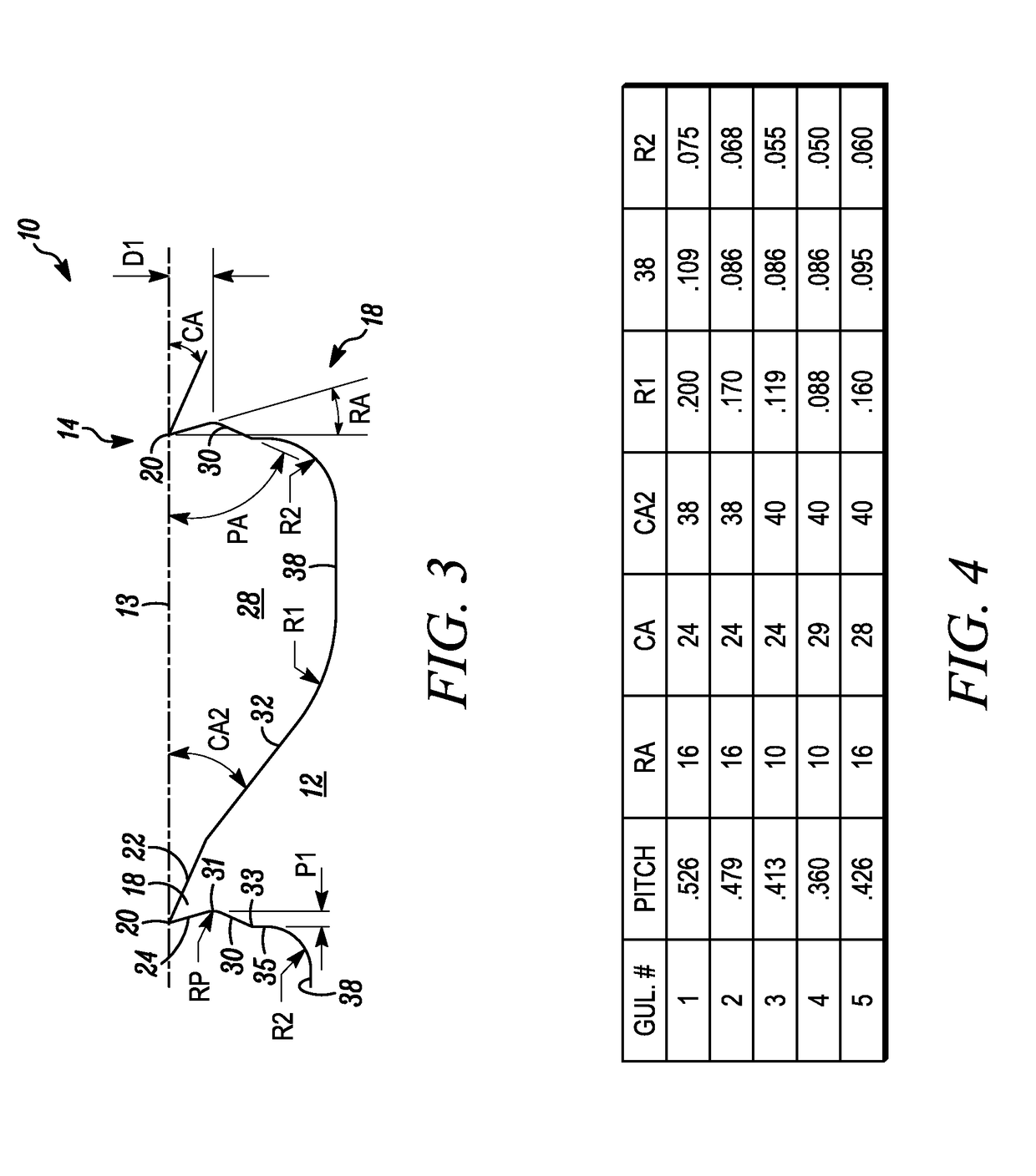
[0025]Referring to FIG. 3, each tooth 18 includes a tip 20, a primary clearance surface 22 located on one side of the tip, a rake face 24 located on an opposite...


PUM

PropertyMeasurementUnit
acute angleaaaaaaaaaa
rake angleaaaaaaaaaa

Abstract

A saw blade, such as a metal-cutting band saw blade, has a cutting edge including a plurality of teeth. A plurality of the teeth include a tip, a clearance surface located on one side of the tip, a rake face located on an opposite side of the tip relative to the clearance surface, a gullet, and a substantially flat, linear, or non-curvilinear projection formed between the rake face and the gullet and projecting outwardly relative to the rake face. The projection is inclined at an acute angle relative to a plane extending between the tips of consecutive unset teeth. The projection defines an inner end adjacent to the rake face and an outer end adjacent to the gullet. The inner end is located at a depth below the tip of at least about 25 / 1000 inch, and the distance between the inner end and the outer end of the projection in a direction substantially parallel to the plane extending between the tips of at least two teeth is less than about 65 / 1000 inch.

Description

FIELD OF THE INVENTION[0001]The present invention relates to saw blades, and more particularly, relates to metal-cutting saw blades, such as band saw blades or hole cutters, for cutting difficult-to-cut materials.BACKGROUND[0002]One of the drawbacks of prior art band saw blades, particularly band saw blades that are used to cut difficult-to-cut materials, such as tool steels, stainless steels, nickel-based alloys, or other hardened or work hardened materials and / or materials that exhibit relatively high shear stress, is that the blade life is not as long as desired and / or the blades do not cut the materials as straight as desired. Current band saw blade designs attempt to overcome these drawbacks by using two distinct methodologies. One approach has been to apply extreme rake angles to traditional tooth / set geometries, without differentiating between “kerf-generating” and “non-kerf-generating” tooth features. Another approach has been to incorporate a “radius” feature on the rake fa...

Claims


Application Information

Patent Timeline
Patent Type & Authority Patents(United States)
IPC IPC(8): B23D61/12
CPCB23D61/121Y10T83/935Y10T83/9317Y10T83/9319Y10T408/895B23D61/12
Inventor CRANNA, MARK T.
Owner BLACK & DECKER INC
Why Eureka
Try Eureka