
Projected capacitive touch panel with silver-inclusive transparent conducting layer(s), and/or method of making the same

a capacitive touch panel and transparent conducting layer technology, applied in the field of projected capacitive touch panel and/or a method of making the same, can solve the problems of increasing production costs and/or time, burdening the manufacturing process, and reducing the durability of the panel, so as to achieve the effect of increasing durability

Inactive Publication Date: 2017-08-15
GUARDIAN GLASS LLC
View PDF19 Cites 27 Cited by
  • Summary
  • Abstract
  • Description
  • Claims
  • Application Information

AI Technical Summary

Benefits of technology

This patent text describes a capacitive touch panel that uses less expensive and more readily usable low-emmissivity coatings to create a large area transparent touch electrode that can handle multi-touch points. The technical effect of this design is to offer a more cost-effective and efficient solution for creating touch panels that offer improved durability and usability.

Problems solved by technology

As the human body is also an electrical conductor, touching the surface of the panel results in a distortion of the panel's electrostatic field, measurable as a change in capacitance.
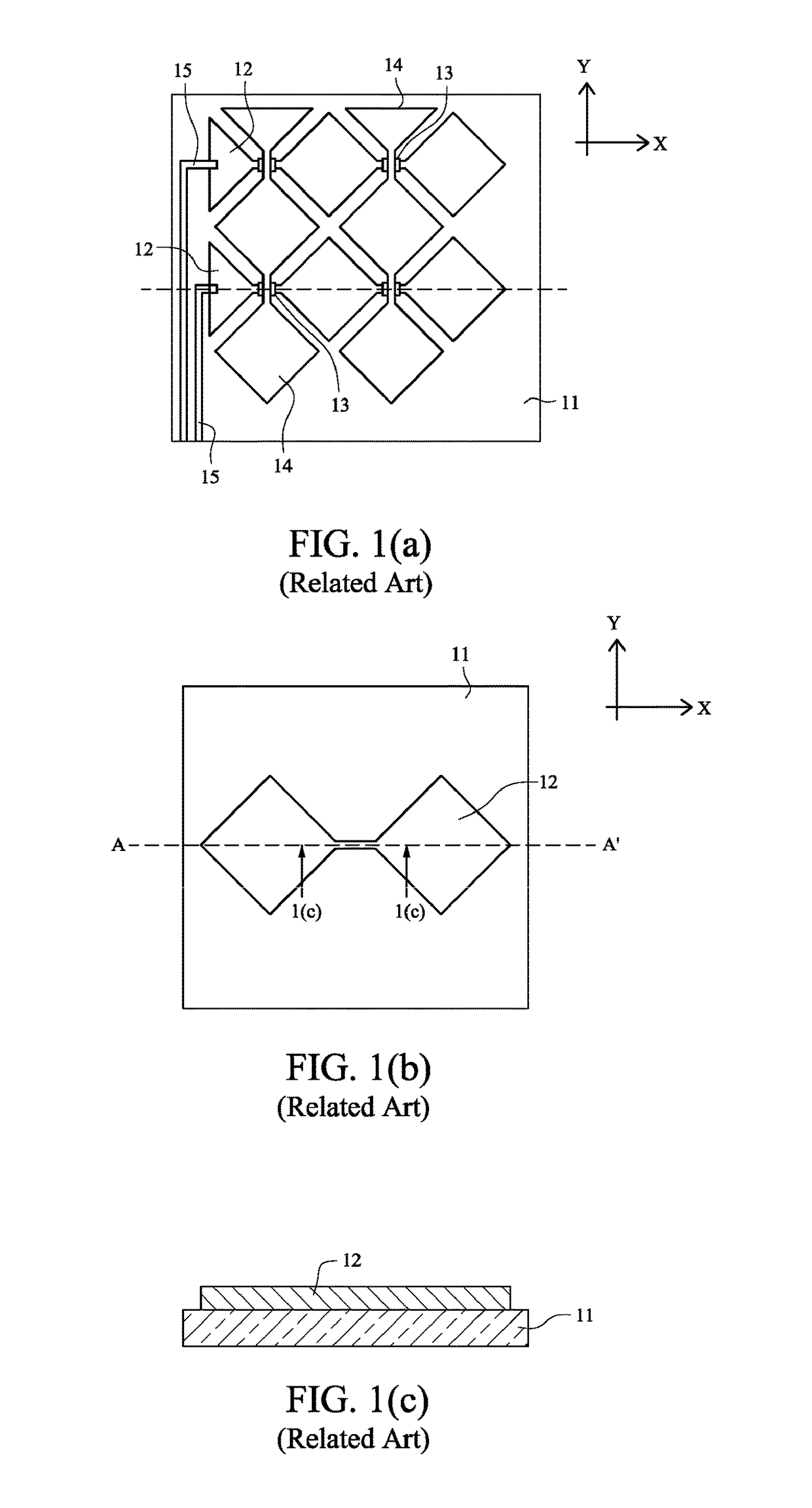
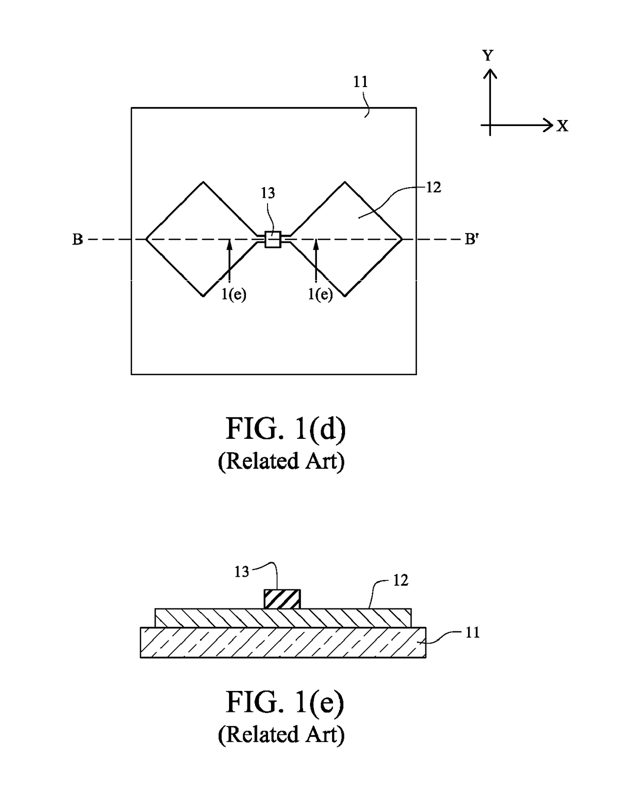
It will be appreciated that the process of manufacturing the structure shown in FIGS. 1(a)-(g) requires three deposition steps and three photolithography type processes, which can render the process of manufacture burdensome, inefficient, and costly.
And each thin film layer typically has its own photolithography and / or laser patterning process, which can increase production costs and / or time.
Thus, the high sheet resistance of thin layers of ITO can limit its use in layouts requiring long narrow traces on large format touch panels (for example, panels with a diagonal measurement of more than 5 inches).

Method used


Image

  • Projected capacitive touch panel with silver-inclusive transparent conducting layer(s), and/or method of making the same
  • Projected capacitive touch panel with silver-inclusive transparent conducting layer(s), and/or method of making the same
  • Projected capacitive touch panel with silver-inclusive transparent conducting layer(s), and/or method of making the same

Examples


Embodiment Construction

[0031]A detailed description of certain example embodiments is provided with reference to the accompanying drawings. Like reference numerals indicate like parts throughout the drawings.

[0032]FIG. 2(a) illustrates a top / bottom plan layout of a projected capacitive touch panel according to an example embodiment of this invention. Referring to FIG. 2(a), touch panel 20 is provided. Touch panel 20 includes a matrix of electrodes including n columns and m rows, provided on a substrate 40. The matrix of row / column electrodes is typically provided on the side of the substrate (e.g., glass substrate 40) that is opposite the side touched by person(s) using the touch panel. In other words, when the touch panel is touched by a finger, stylus, or the like, the substrate 40 is typically located between the finger and the matrix of row / column electrodes. A change in capacitance between adjacent row and column electrodes in the matrix as a result of the proximity of a finger or the like is sensed ...


PUM

PropertyMeasurementUnit
sheet resistanceaaaaaaaaaa
sheet resistancesaaaaaaaaaa
sheet resistanceaaaaaaaaaa

Abstract

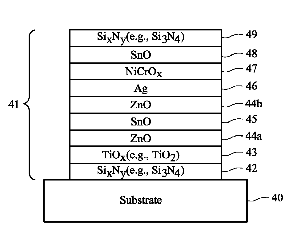
Certain example embodiments relate to capacitive touch panels. First and second glass substrates are substantially parallel and spaced apart from one another. At least one multi-layer transparent conductive coating (TCC) is patterned into electrodes and located between the first and second substrates. The TCC(s) include(s) at least one conductive layer including silver, a dielectric layer including zinc oxide under and directly contacting the conductive layer including silver, and a dielectric layer(s) including tin oxide or silicon nitride over the conductive layer including silver. Processing circuitry electrically connects to the electrodes and measures an aspect of the electrodes' capacitance. A laminate material is located between the first and second glass substrates. The TCC(s), when blanket deposited, may have a visible transmission of at least 88%, a sheet resistances of no more than 10 ohms per square, and a haze of no more than 0.5%. Mutual and self-capacitance designs are disclosed.

Description

CROSS-REFERENCE TO RELATED APPLICATION[0001]This application is a continuation-in-part (CIP) of U.S. application Ser. No. 15 / 146,270 filed on May 4, 2016, which is a continuation of U.S. application Ser. No. 13 / 685,871 filed on Nov. 27, 2012, now U.S. Pat. No. 9,354,755, the entire contents of each of which are hereby incorporated herein by reference.TECHNICAL FIELD[0002]Certain example embodiments relate to a projected capacitive touch panel, and / or a method of making the same. More particularly, certain example embodiments relate to a projected capacitive touch panel with a silver-inclusive transparent conducting layer(s), and / or a method of making the same.BACKGROUND AND SUMMARY[0003]A capacitive touch panel includes an insulator such as glass, coated with a conductive coating. As the human body is also an electrical conductor, touching the surface of the panel results in a distortion of the panel's electrostatic field, measurable as a change in capacitance. A transparent touch p...

Claims


Application Information

Patent Timeline
Patent Type & Authority Patents(United States)
IPC IPC(8): G06F3/044G02F1/1333G06F3/041
CPCG06F3/044G02F1/13338G06F3/0412G06F2203/04103G06F3/0443G06F3/0446G06F3/0445C03C17/3626C03C17/3644
Inventor VEERASAMY, VIJAYEN S.BLUSH, JASONAKKASHIAN, ERIC W.DEN BOER, WILLEMKRASNOV, ALEXEY
Owner GUARDIAN GLASS LLC
Learn More