Rotary electric device for power working machine

a technology of rotary electric device and working machine, which is applied in the direction of mechanical energy handling, magnetic circuit rotating parts, magnetic circuit shape/form/construction, etc., can solve the problem that the heat is hardly transmitted to the cover

Active Publication Date: 2017-08-15
TOYO DENSO CO LTD +1
View PDF9 Cites 1 Cited by
  • Summary
  • Abstract
  • Description
  • Claims
  • Application Information

AI Technical Summary

Benefits of technology

[0007]The present invention has been made with the foregoing situations taken into consideration. An object of the present invention is to provide a rotary electric device for a power working machine which is capable of simultaneously solving the foregoing problems using a simple structure.
[0009]According to the first aspect of the present invention, the rotary electric device for a power working machine, which is capable of being braked by the brake mechanism, is configured as follows. The yoke connected to the crankshaft of the engine is covered with the cover having a bottomed cylindrical shape. The cover includes: the cover cylindrical portion concentrically surrounding the outer peripheral surface of the cylindrical portion of the yoke with the annular clearance interposed therebetween, and having the outer peripheral surface with which the brake shoe is capable of being placed in pressure contact; and the cover bottom wall portion continuous to the one end of the cover cylindrical portion, and connected to the bottom wall portion of the yoke. The ventilation clearance communicating with the annular clearance is formed between the bottom wall portion of the yoke and the cover bottom wall portion. The vent holes communicating the ventilation clearance with the outside of the yoke are provided through the bottom wall portion of the yoke and the cover bottom wall portion. For these reasons, even when the temperature of the cover which functions as the brake drum is increased by friction during braking operation, or the cover is deformed due to braking load, influence of the heat and deformation on the yoke can be effectively inhibited, and deterioration in performance of the rotary electric device can be prevented. In addition, even if the temperature of the yoke becomes high due to heat generated from coils, the magnet and the like when the rotary electric device is operated, the heat is hardly transmitted to the cover. For this reason, deterioration in brake performance due to the operation heat of the rotary electric device can be prevented. Furthermore, cooling air can be made to flow to: the clearances (the annular clearance and the ventilation clearance) formed between the yoke and the cover; and the vent holes provided through the bottom wall portion of the yoke and the bottom wall portion of the cover. In addition, surface areas of the yoke and the cover can be sufficiently secured as a whole. For these reasons, the yoke and the cover can be effectively cooled. Thereby, it is unnecessary to, for example, especially provide a magnet protection cover between an inner periphery of the yoke and the magnet and especially thicken the yoke itself. It is possible to contribute to: cost reduction; reduction in the weight of rotary portions of the rotary electric device; and accordingly reduction in fuel consumption of the engine and reduction in inertial mass of the engine.
[0011]According to the second aspect of the present invention, the cooling fan for making the cooling air forcedly flow in the annular clearance, the ventilation clearance and the vent holes is connected to the outer surface of the cover bottom wall portion. For this reason, by making the cooling air forcedly flow in the clearances between the yoke and the cover, a cooling effect on the yoke and the cover can be further enhanced.
[0013]According to the third aspect of the present invention, the bottom wall portion of the yoke and the cover bottom wall portion are connected to each other with the hub interposed therebetween, and the boss portion integral with the hub is connected to the crankshaft. For these reasons, the yoke and the cover are connected and integrated with each other via the common hub so as to be able to be made into a sub-assembly. Accordingly, workability of attaching and detaching the yoke and the cover to and from the crankshaft is satisfactory. Furthermore, the use of the hub interposed between the yoke and the cover makes it possible to position the yoke and the cover to each other accurately and easily, and to set the clearances therebetween accurately and easily.

Problems solved by technology

In addition, even if the temperature of the yoke becomes high due to heat generated from coils, the magnet and the like when the rotary electric device is operated, the heat is hardly transmitted to the cover.

Method used


Image

  • Rotary electric device for power working machine
  • Rotary electric device for power working machine
  • Rotary electric device for power working machine

Examples


Embodiment Construction

[0019]Descriptions will be hereinbelow provided for an embodiment of the present invention on the basis of a preferable embodiment of the present invention shown in the accompanying drawings.

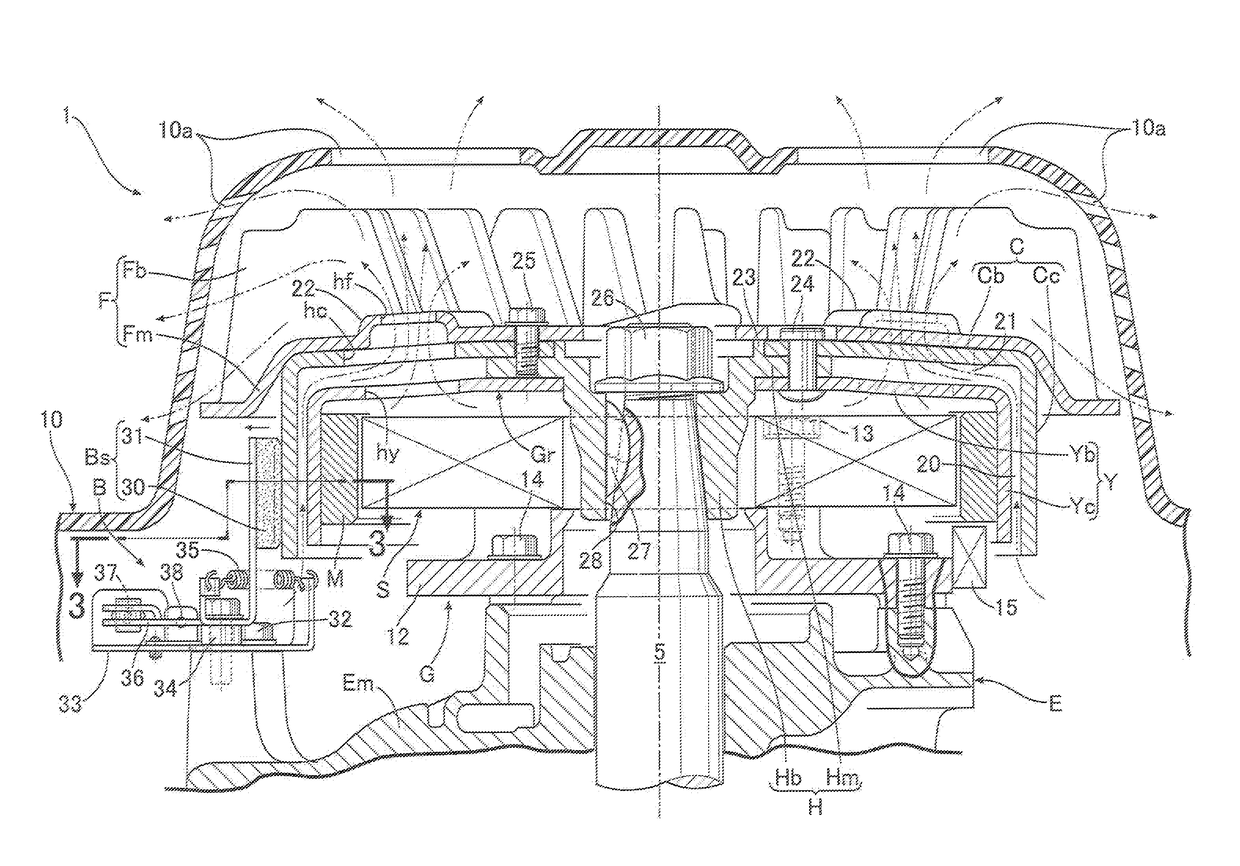
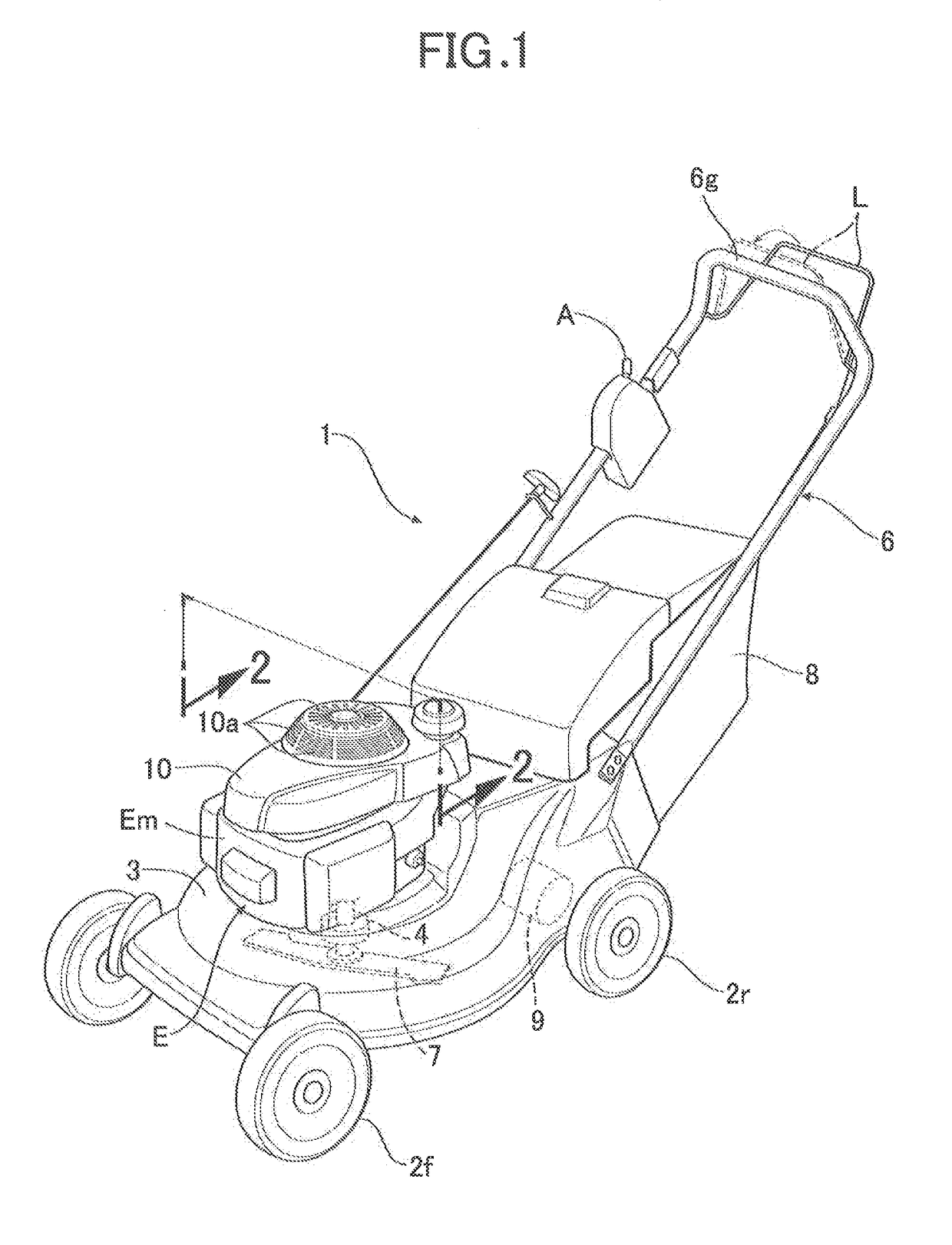
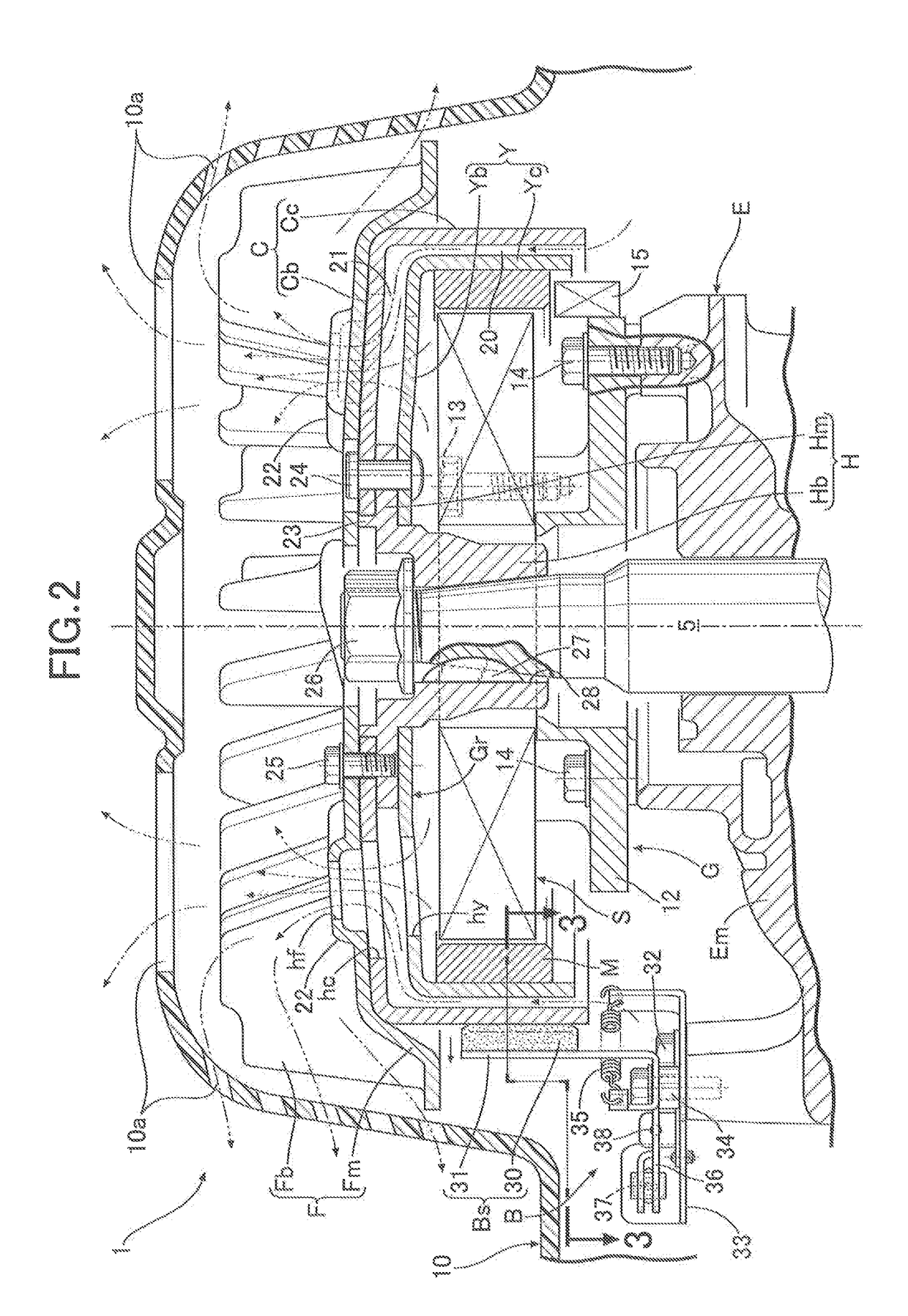
[0020]First of all, in FIG. 1, a walking-type power mower 1 as a power working machine includes a housing 3 having an opened lower surface and supported by front wheels 2f and rear wheels 2r. A vertical engine E having a crankshaft 5 arranged in a vertical direction is mounted on an upper portion of the housing 3. A rotary cutting blade 7 arranged inside the housing 3 is connected to a lower end of the crankshaft 5 via an electromagnetic clutch 4. A lawn bag 8 is attached to a steering handle 6 which is connected to a rear end of the housing 3 so as to extend obliquely rearward. Lawn grass cut by the cutting blade 7 is stored into the lawn bag 8. It should be noted that: in the embodiment, the rear wheels 2r are driven by a traveling motor 9; and the traveling motor 9 and a battery (not illustra...


PUM


Abstract

In a rotary electric device for a power working machine capable of being braked by a brake mechanism, a cover having a bottomed cylindrical shape and covering a yoke of the device, includes: a cover cylindrical portion concentrically surrounding an outer peripheral surface of a cylindrical portion of the yoke with an annular clearance therebetween, and having an outer peripheral surface with which a brake shoe is capable of being placed in pressure contact; and a cover bottom wall portion continuous to one end of the cover cylindrical portion, and connected to a bottom wall portion of the yoke. A ventilation clearance communicating with the annular clearance is formed between the bottom wall portion and the cover bottom wall portion. Vent holes communicating the ventilation clearance with an outside of the yoke are provided through the bottom wall portion and the cover bottom wall portion.

Description

BACKGROUND OF THE INVENTION[0001]Field of the Invention[0002]The present invention relates to a rotary electric device for a power working machine, which is operatively connected to an engine as a power source for the power working machine such as a power mower and the like, and capable of being braked by a brake mechanism.[0003]Description of the Related Art[0004]As disclosed in, for example, Japanese Patent Application Laid-open No. 2005-282552, a technique has been known in which a brake shoe of a brake mechanism is placed in pressure contact with functional components, such as a flywheel and the like, which are operatively connected to the engine capable of driving a cutting blade, so that a crankshaft of the engine can be braked.[0005]In the power working machine as described above, in a case where as an object to be braked by the brake mechanism, for example, a rotor of a rotary electric device, particularly, a yoke having a bottomed cylindrical shape, is selected in place of ...

Claims


Application Information

Patent Timeline
Patent Type & Authority Patents(United States)
IPC IPC(8): H02K1/32A01D34/68H02K9/06H02K21/22H02K7/102H02K7/02H02K7/18H02K1/30
CPCH02K9/06A01D34/6812H02K1/32H02K7/102H02K21/222H02K1/30H02K7/02H02K7/1815
Inventor ENDO, TAKEHIKOSHIMIZU, NAOAKIYANOI, SATOSHITAKAHASHI, MASAKIYAMAGISHI, YOSHIHIKO
Owner TOYO DENSO CO LTD
Why Eureka
Try Eureka